This problem is solved in that a resistance heating element with printed conductors applied to a
dielectric is fitted on the base of the mixing vessel, the generally circular, disk-shaped heating element having a central recess which is adapted to the dome. As a result of this configuration, the mixing vessel and the food contained in it are heated directly. There are smaller losses in comparison with the known prior art. The heat introduced is transferred directly into the food. Furthermore, by dispensing with large masses for heating, the
controllability of the
heating system is improved and the heating-up rate is increased. What is more, uniform temperature distribution is made possible by disposing the heating element in a specific way. On account of the increased efficiency, the required electrical power is minimized, whereby the prescribed duty cycles are shortened, with an accompanying increase in the control accuracy. It also proves to be advantageous that the way in which the resistance heating element is disposed and configured according to the invention makes the construction less susceptible to tolerances in comparison with conventional systems, in which known systems an exact engagement between the mixing vessel and the heating is required.
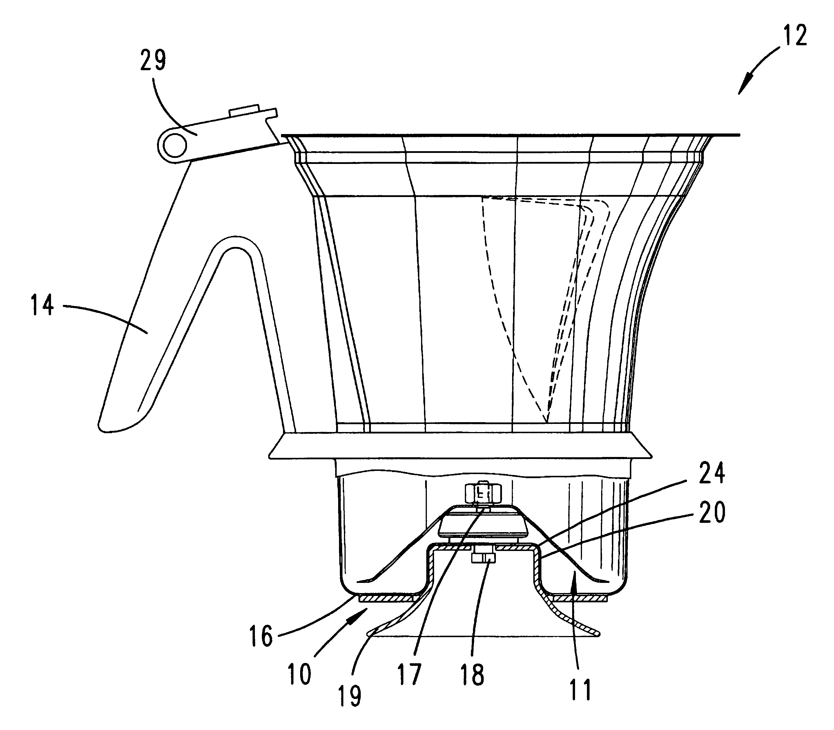
The invention also relates to a food processor with a mixing vessel and a drive for an agitator in the mixing vessel, the mixing vessel being heatable in its lower region and having on the bottom a dome which has the securing mount for the agitator. Here, for the advantageous further development of a food processor of the type in question, it is provided that a resistance heating element with printed conductors enveloped by a
dielectric is fitted on the base of the mixing vessel. For example, a tubular heating element which is enveloped by a dielectric and is secured on the base of the mixing vessel may be provided here. Here, too, the food is heated directly, with the
advantage of a lower loss, since the heat introduced is transferred directly into the food. What is more, the
controllability of the
heating system is improved and the heating-up rate is increased.
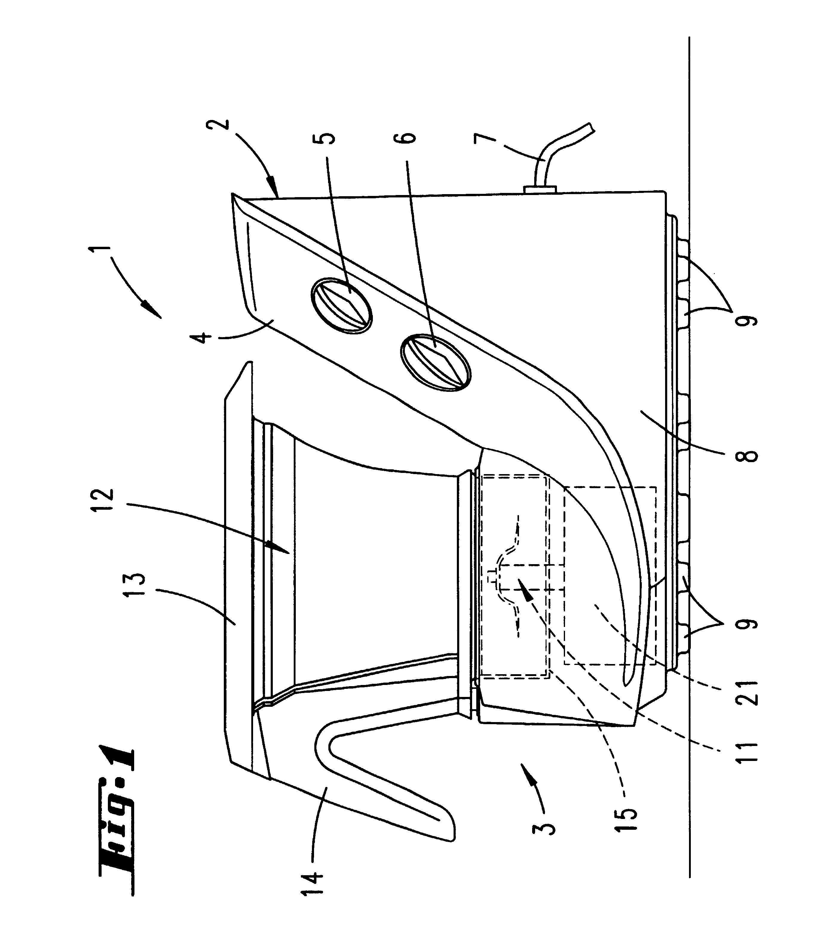
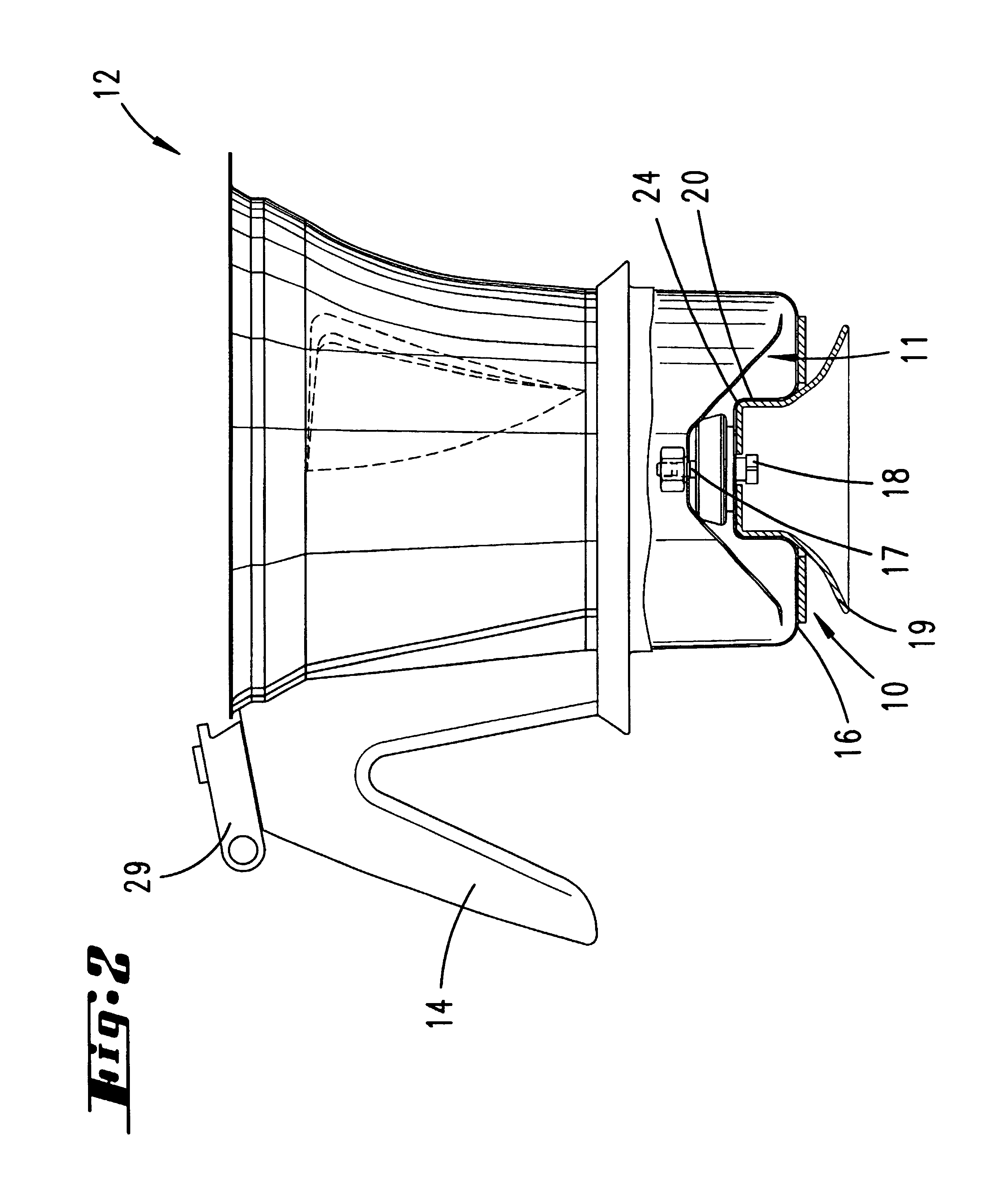
The invention also relates to a food processor with a mixing vessel and a drive for an agitator in the mixing vessel, the mixing vessel being heatable in its lower region and having on the bottom a dome which has the securing mount for the agitator. Here it is proposed for the advantageous development of the
subject matter of the invention that externally shielded
microwave radiators are disposed outside the mixing vessel, associated with the bottom region. As a result of this configuration, contactless heating is provided for a food processor of the type in question, which is suitable for chopping up,
grinding and pulverizing, beating, mixing, slow cooking, emulsifying and
steaming. It proves to be particularly advantageous here that the
microwave radiators comprise annular
quartz-glass radiators which operate in the
medium wave range and are disposed one above the other, so that a broad ring around the mixing vessel is created, with a defined distance from the outer surface of the mixing vessel. In this respect, a plurality of separately activatable
quartz-glass radiators are preferably provided, that is again for example four annular
quartz-glass radiators. The heating elements formed in this way can consequently be activated together, or else independently of one another, making optimized control possible. In addition, it is proposed that the mixing vessel is provided on the outer side of its lower region with a surface with active
radiation absorption, which again for example is formed as a black
coating. To provide heat protection from the interior of the appliance, it is provided that the
microwave radiators are surrounded by a cooling duct. The latter is, in addition, preferably formed as an air duct with a through-flow.

