Multi-output switching power source circuit

a power supply circuit and multi-output technology, applied in the direction of electric variable regulation, process and machine control, instruments, etc., can solve the problems of reducing conversion or transformation efficiency of diodes, reducing the overall loss of power source circuits including such diodes, and reducing conversion loss

Inactive Publication Date: 2003-11-04
NEC PLATFORMS LTD
View PDF4 Cites 11 Cited by
  • Summary
  • Abstract
  • Description
  • Claims
  • Application Information

AI Technical Summary

Problems solved by technology

The use of such a diode in the rectifier circuit leads to a problem that power loss due to a voltage drop in the diode lowers conversion or transformation efficiency.
There also arises a problem as below.
However, the voltage drop of the diode is almost fixed, about, 0.4 V. This consequently results in a problem.
That is, when the output voltage of the power supply circuit is reduced, the power loss in the rectifier circuit including such a diode becomes relatively larger in the overall loss in the power source circuit.
This further lowers the conversion loss and hinders the lowering of the output voltage.
This leads to a problem that the dummy resistor continuously requires power and hence the power efficiency is lowered.
This leads to an additional problem.

Method used


Image

  • Multi-output switching power source circuit
  • Multi-output switching power source circuit
  • Multi-output switching power source circuit

Examples


first embodiment

FIG. 8 shows a configuration of electric connections of an embodiment of the a multi-output switching power source circuit in accordance with the present invention. Description will now be given in detail of the embodiment by referring to FIG. 8.

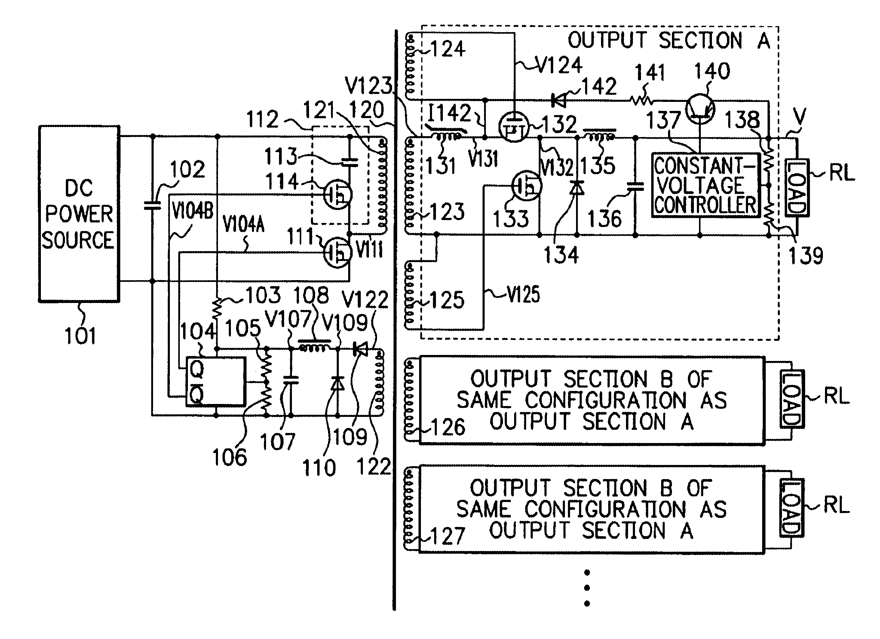
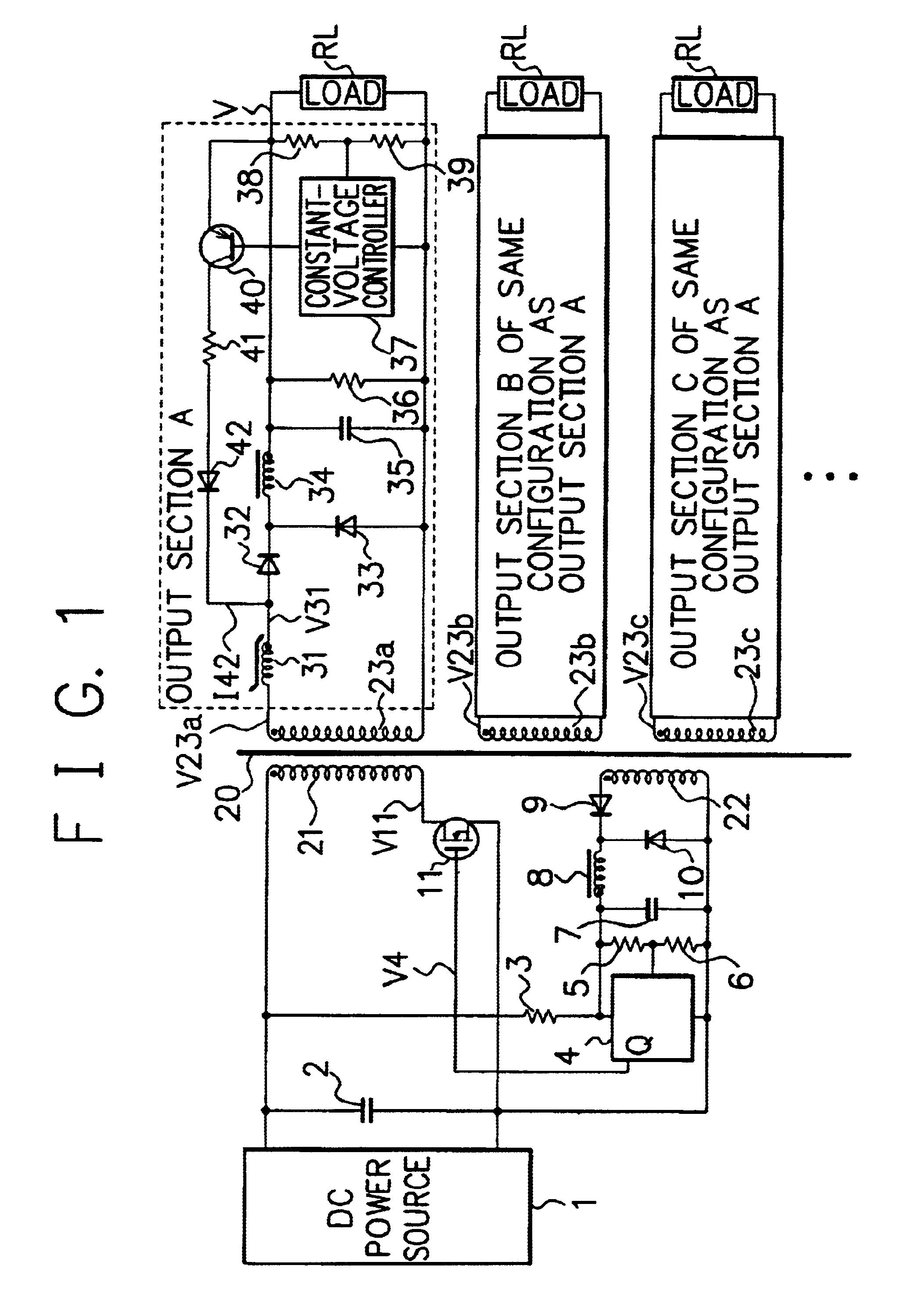
The multi-output switching power circuit in accordance with the present invention is adopted a forward converter type and includes a switching circuit(s) which is produced a predetermined ac voltage in a primary winding and an auxiliary winding 122 by applying an input voltage from a dc power source(s) and on / off controlling by the transistor 111.

The configuration of the power source circuit includes a transformer 120 having a primary side and a secondary side. The circuit includes on the primary side a dc power source 101, an input smoothing capacitor 102, a starting resistor 103, a PWM control circuit 104, detecting resistors 105 and 106, a capacitor 107, a smoothing choke coil 108, a rectifying diode 109, a commutating diode 110, a switch...

second embodiment

The second embodiment configured as above is effectively applicable when there exists a large-current output which cannot be controlled by a magnetic amplifier. The second embodiment can also obtain an advantageous effect similar to that of the first embodiment.

Third Embodiment

Referring now to the accompanying drawings, description will be given of a third embodiment in accordance with the present invention. FIG. 14 shows a configuration of the third embodiment of the present invention.

third embodiment

The third embodiment and the first embodiment are configured basically in the same way. The third embodiment includes a devised configuration of an NMOS synchronous rectifying circuit and a magnetic amplifier control circuit.

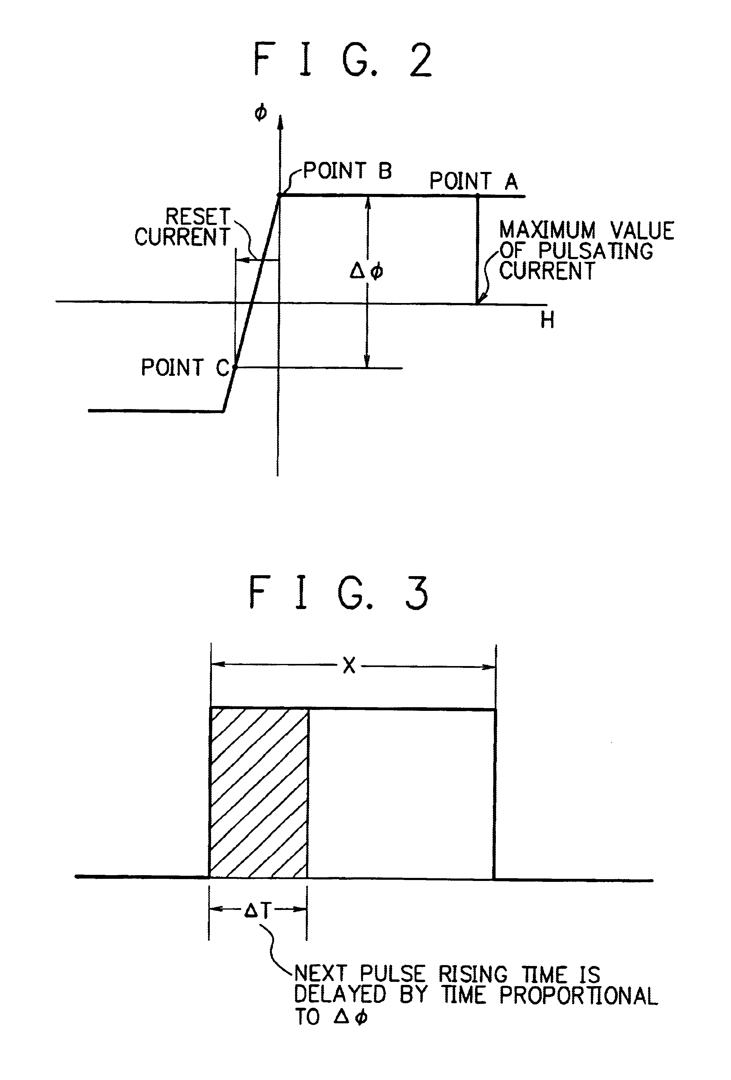
In the third embodiment, an NMOS 342 and an NMOS 343 for synchronous rectification are driven by a voltage generated by a secondary winding 323, and a magnetic amplifier is arranged between a gate electrode of the NMOS 342 on a rectification side and a drain electrode of the NMOS 343 on a commutation side. The magnetic amplifier 341 additionally includes a reset winding to reset the core of the amplifier 341. A constant-voltage circuit 347 supplies a reset current to a winding start point of the reset winding to be delivered via the NMOS 342 to a ground side in a subsequent stage. Therefore, the loop to flow the reset current does not include the NMOS 342 for synchronous rectification. The magnetic amplifier can be turned on or off without any influence from the...


PUM


Abstract

A multi-output switching power supply circuit easily produces multiple outputs with increased power source conversion efficiency. The circuit includes, in place of the rectifying diode and the commutating diode used in the multi-output switching power supply circuit of the prior art, a circuit configuration in which an NMOS for synchronous rectification is combined with a constant-voltage control by a magnetic amplifier. It is not required to use, for example, a radiator to dissipate heat, and hence the system size is reduced and the conversion efficiency is increased, and the system can be easily implemented in a low-voltage multi-output configuration. In a configuration in which a magnetic amplifier is arranged between a secondary winding and an first NMOS for synchronous rectification and a drive circuit for the first NMOS and an second NMOS for synchronous rectification is implemented as a separate winding other than the secondary winding, the first NMOS is not included in a loop to flow a reset current. The magnetic amplifier can conduct constant-voltage control without any influence from the interruption of the control loop when the first NMOS on the rectifying side is turned off.

Description

The present invention relates to a multi-output switching power source circuit to conduct constant-voltage control using a magnetic amplifier or a magamp.Description of the Prior ArtFIG. 1 shows a conventional circuit configuration of a multi-output switching power supply circuit to conduct constant-voltage control using a magnetic amplifier or a transducer.The power supply 20 includes a transformer 20 including a primary side which includes a direct-current (dc) power source 1, an input smoothing condenser or capacitor 2, a starting resistor 3, a pulse width modulation controller 4, detecting resistors 5 and 6, a capacitor 7, a smoothing choke coil 8, a rectifying diode 9, a commutating diode 10, and a main switch 11, e.g., an n-type metal-oxide semiconductor transistor (to be simply referred to as an NMOS hereinbelow).On the primary side of the transformer 20, a primary winding 21 and an auxiliary winding 22 are disposed. The transformer 20 includes a secondary side including seco...

Claims


Application Information

Patent Timeline
Patent Type & Authority Patents(United States)
IPC IPC(8): H02M3/24H02M3/335H02M1/16
CPCH02M1/16H02M3/33592H02M3/33561Y02B70/1475Y02B70/10
Inventor WATANABE, KIYOHIKO
Owner NEC PLATFORMS LTD
Why Eureka
Try Eureka