
Advanced combined cycle co-generation abatement system

Inactive Publication Date: 2003-12-02
SARDARI AMIR A
View PDF30 Cites 81 Cited by
  • Summary
  • Abstract
  • Description
  • Claims
  • Application Information

AI Technical Summary

Problems solved by technology

As a result, the steady increase in releases of these compounds has leveled off and in some areas has declined.
Unfortunately, solvent vaporization and hydrocarbon byproducts are key to many manufacturing processes that are critical to everyday life.
While the control of these VOC's is essential to the safety of the environment, a cost effective means for control of these compounds remains a struggle within the always competitive manufacturing industry.
These thermal oxidizers are complicated devices which represent a huge capital expense and the operating costs of which typically increase the yearly energy cost in excess of 25%.
Such control systems result in a substantial amount of energy being wasted by exhausting hot flue gases to the atmosphere.
Moreover, previous systems utilized very severe conditions which often involved unneeded combustion, which combustion itself often resulted in unnecessary air pollution.
As can be expected, the costs of such an operation are significantly more expensive than a thermal oxidizer system, and thus, such a system is less attractive for the typical industrial business.

Method used


Image

  • Advanced combined cycle co-generation abatement system
  • Advanced combined cycle co-generation abatement system
  • Advanced combined cycle co-generation abatement system

Examples


Embodiment Construction

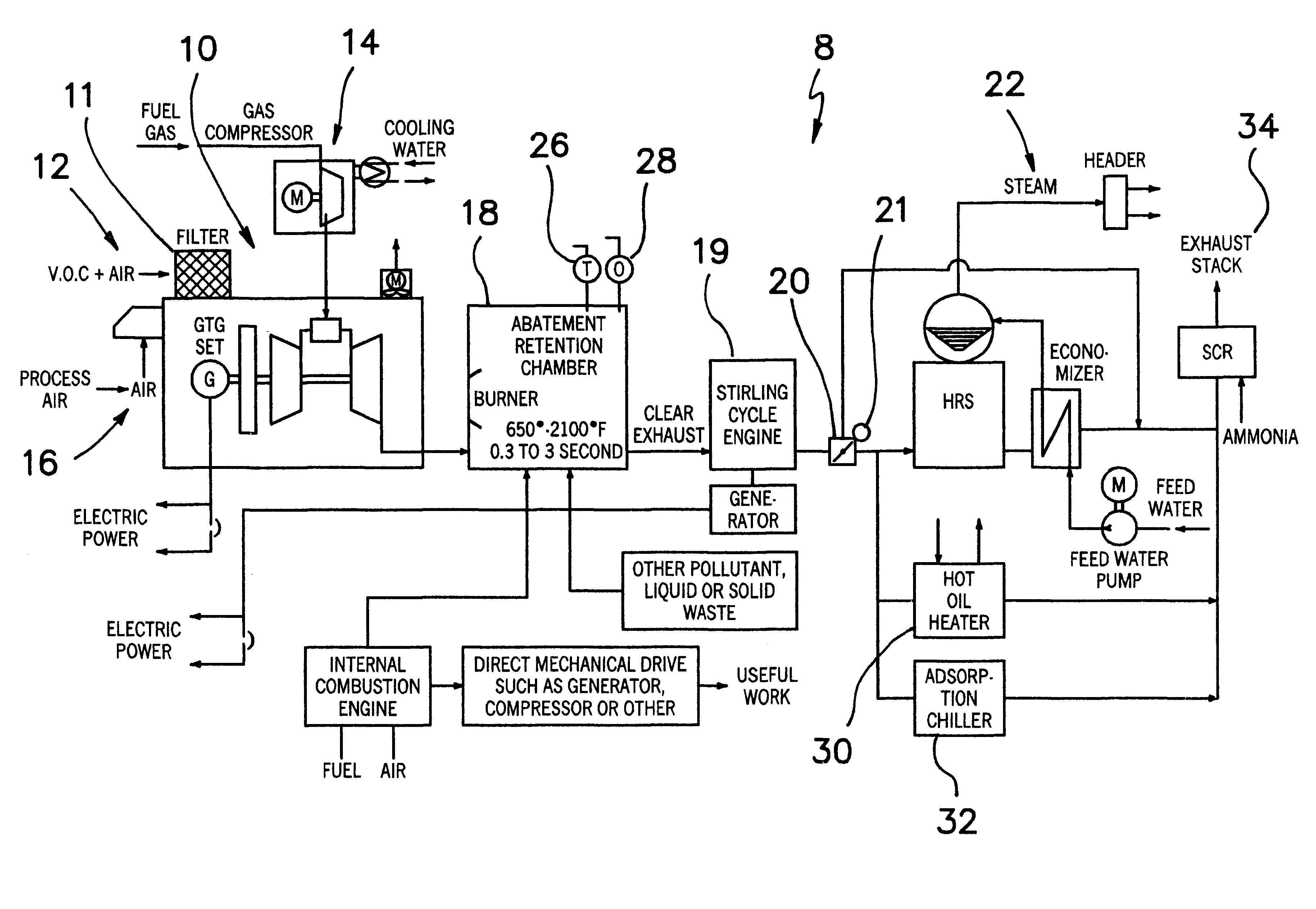
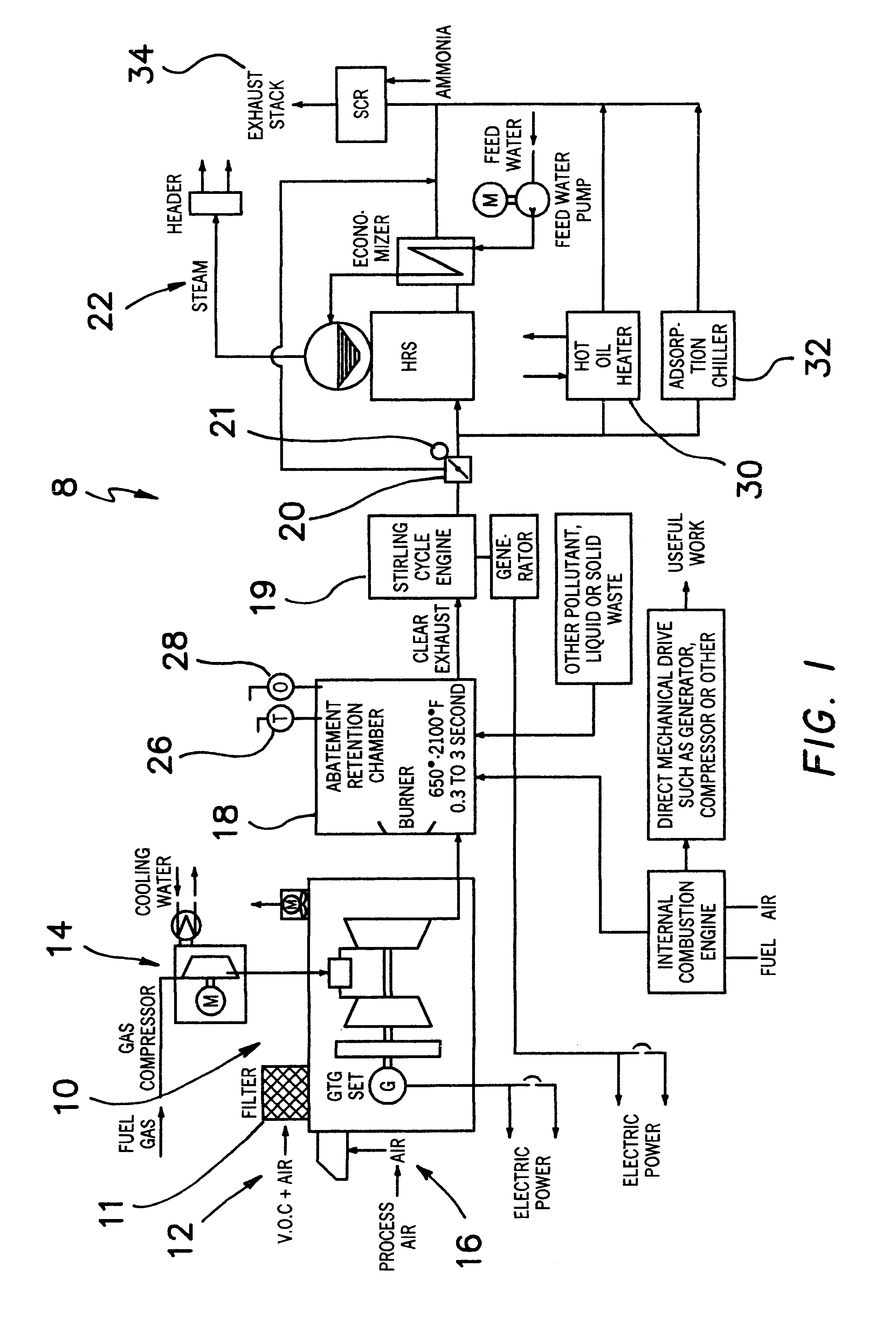
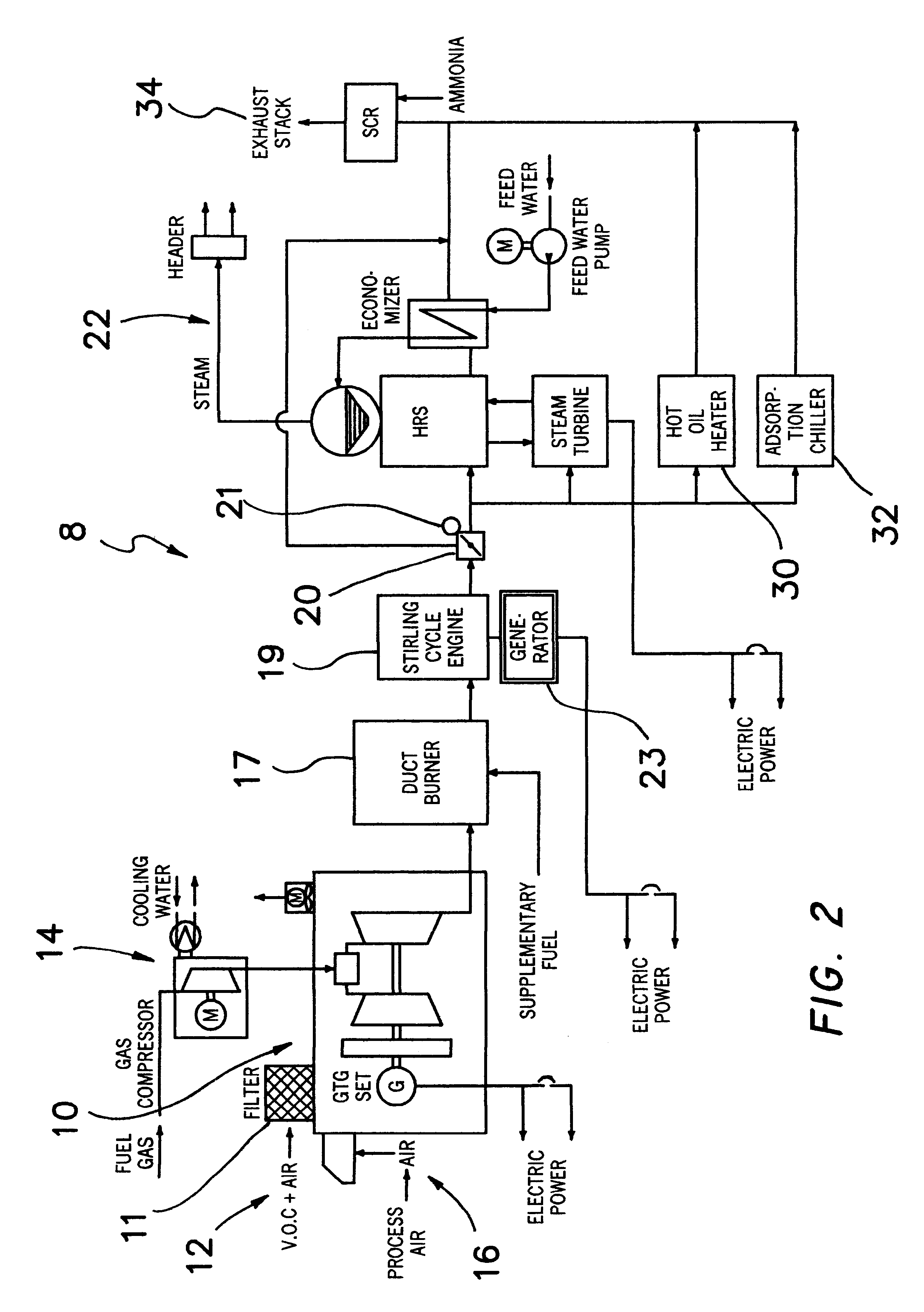
In the preferred embodiment of the advanced combined co-generation solid waste and VOC abatement system, generally identified as 8, in accordance with the present invention, includes a thermal oxidation apparatus, shown generally at 10, an abatement retention chamber 18, a Stirling cycle engine 19, an exhaust damper 20 and a boiler section, shown generally at 22. The thermal oxidation apparatus 10 further includes a gas intake assembly 12, a fuel intake assembly 14, and an air intake assembly 16.

Referring to FIG. 1, the combined system 8 is controlled, as discussed in detail hereinafter, from a centralized control panel, not shown. The various components of the control panel may be selected from conventional and commercially available components which individually or together are useful to receive and transmit the control signals and alarm signals described herein. Although each of the parts of the combined system 8 is discussed separately, the proper functioning of the combined sys...


PUM


Abstract

The present invention is an advanced co-generation system for abating solid wastes, hydrocarbons and other volatile organic compounds (VOC's) produced by various processes utilizing a Stirling cycle engine, turbines or other internal combustion engines doing useful work. The turbine exhaust is directed into an abatement chamber which may include a catalyst that is designed to operate at high temperature and includes supplementary fuel and air inputs which are controlled by a computer that receives sensor inputs to achieve the requisite heat ranges necessary to convert exhaust and VOC's to non-toxic substances. The exhaust generated by the abatement chamber is directed to a Stirling cycle engine for additional heat generation and recovery. The exhaust generated from this process can also be used to perform direct or indirect heating.

Description

1. Related ApplicationThis application claims the benefit of U.S. provisional application Serial No. 60 / 300,791 filed Jun. 25, 2001, the disclosure of which is incorporated in its entirety herein by reference.2. Field of the InventionThis invention relates to pollutant abatement generally, and more particularly to a method and apparatus for abating hydrocarbons, volatile organic compounds exhausted by a turbine or other internal combustion engine and solid wastes.3. Description of the Prior ArtAir quality has been an increasing public concern over the past half century. In that time, the scientific community has worked to improve its understanding of the origins of pollutants that predominate in the air of most major cities in the United States. An increasing amount of this air pollution can be attributed to the release of hydrocarbons and other volatile organic compounds (VOC's). As a result, it has become increasingly important to control and reduce the amount of these toxins that...

Claims


Application Information

Patent Timeline
IPC IPC(8): B01D53/86F01N3/26F01N5/00F01N5/02F02G1/00F02G1/043
CPCB01D53/8668F01N3/26F02G1/043F01N5/02Y02T10/16Y02T10/12
Inventor SARDARI, AMIR A.
Owner SARDARI AMIR A
Learn More