
Front panel with an anti-reflection layer having particular compositions

a technology of anti-reflection layer and front panel, which is applied in the field of front panel, can solve the problems of reducing the transmittance of visible rays, reducing the visibility of images, and limit the amount of additives such as dyes or pigments

Inactive Publication Date: 2003-12-02
SUMITOMO CHEM CO LTD
View PDF9 Cites 13 Cited by
  • Summary
  • Abstract
  • Description
  • Claims
  • Application Information

AI Technical Summary

Problems solved by technology

In addition, since a brightness of an image on the said displays is smaller than that on conventional CRT displays, reflection images of environmental objects will decrease the visibility of the image.
This reduces a transmittance of visible rays and, accordingly, there is a limitation in the amount of additive such as dye or pigment.
However,-the anti-reflection plate, where an anti-reflection layer consisting of layers of both high and low optical refractive index values are provided on the surface of the base plate, is poor in scratch-protection ability and the anti-reflection layer tends to be peeled out.
A surface of a display front panel may be smooth or may have minute unevenness.
If the thickness is not more than about 0.5 .mu.m, the scratch-protection ability tends to become insufficient and, if it exceeds about 50 .mu.m, the hard coat layer tends to be cracked.

Method used


Image

  • Front panel with an anti-reflection layer having particular compositions
  • Front panel with an anti-reflection layer having particular compositions
  • Front panel with an anti-reflection layer having particular compositions

Examples


example 1

(1) Forming a Hard Coat Layer

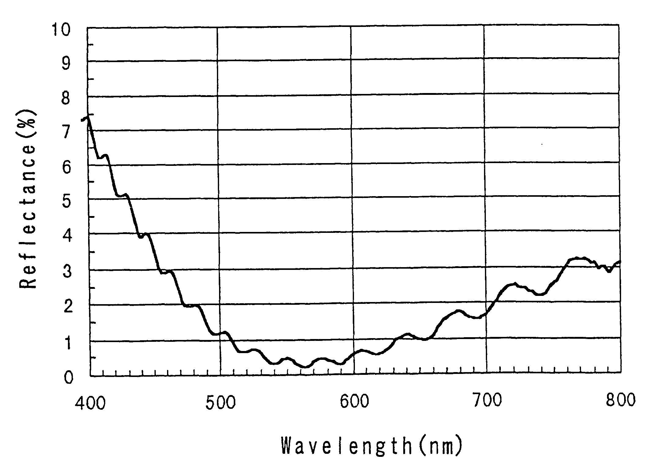
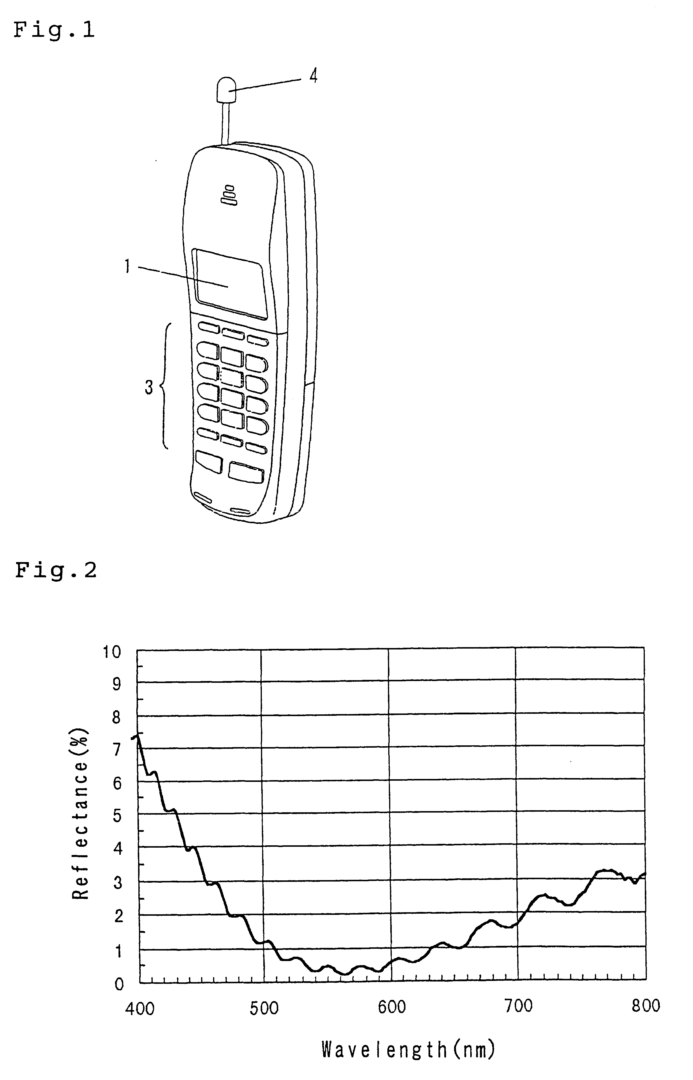
A coating composition for a hard coat layer was formed by mixing 53.6 parts by weight of a marketed hard coat agent containing electro-conductive particles ("SUMICEFINE R-311" manufactured by Sumitomo Osaka Cement Co., Ltd.), 6.9 parts by weight of dipentaerythritol hexaacrylate ("NK ESTER A9530" manufactured by Shin Nakamura Chemical Co., Ltd.), 10.8 parts by weight of methyl ethyl ketone, and 24.2 parts by weight of diacetone alcohol together. By coating this composition for a hard coat layer on the acrylic resin plate ("SUMIPEX E000" of 2 mm in thickness manufactured by Sumitomo Chemical Co., Ltd.) at the lifting speed of 50 cm / minute in the dip coating method and, after drying it at 40.degree. C. for 10 minutes, irradiating an ultraviolet rays, a hard coat layer was provided. This hard coat layer shows an anti-static ability.

(2) Forming a First Layer

A coating composition for a first layer was formed by mixing 1.0 parts by weight of pentaerythritol tr...

example 2

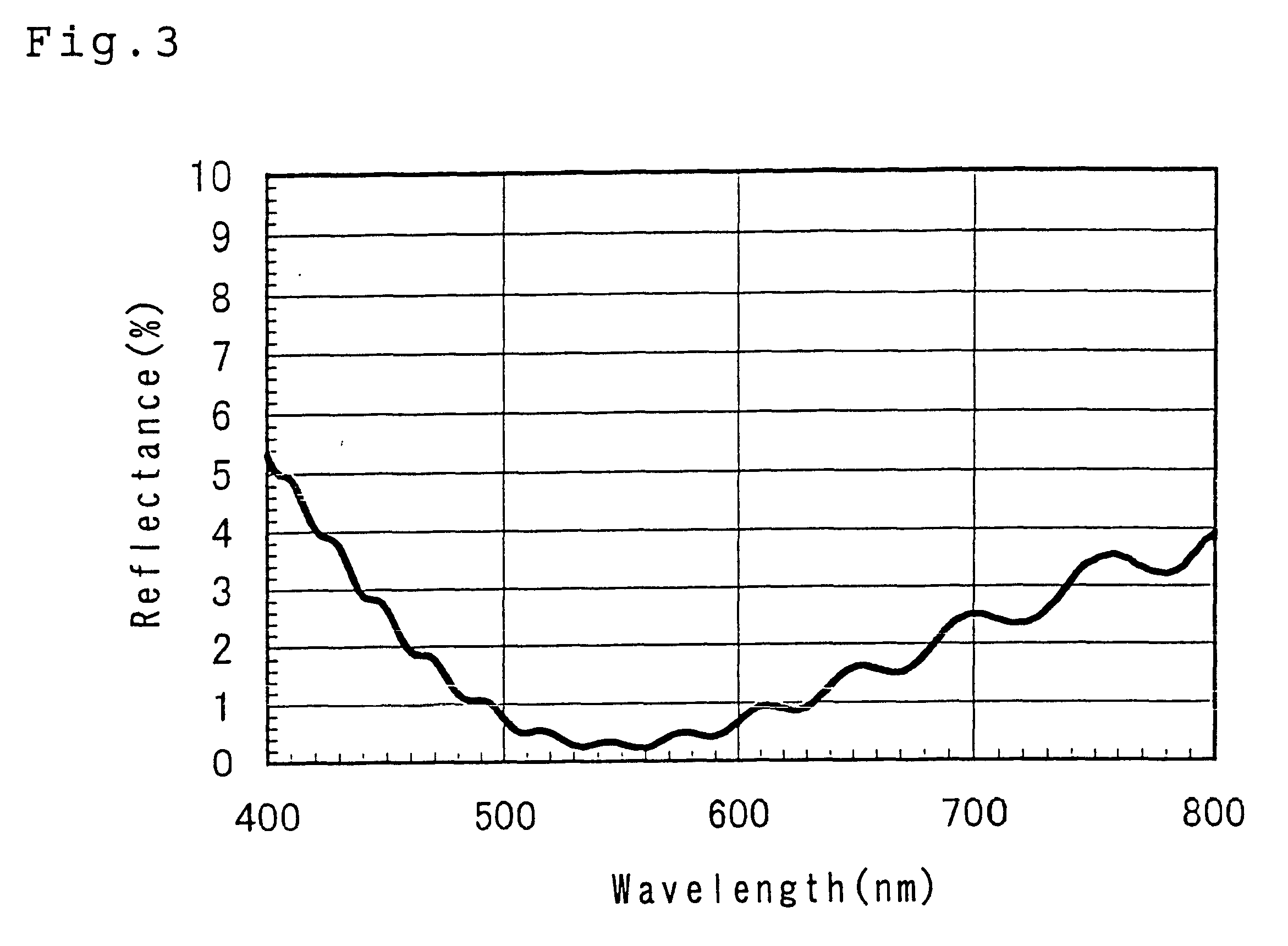
A coating composition for a first layer was formed by mixing 1.7 parts by weight of zirconium dioxide with an average primary particle diameter of 0.01 .mu.m, 1.0 parts by weight of pentaerythritol triacrylate, 0.1 part by weight of tetramethoxysilane oligomer ("MKC SILICATE MS51" placed on sale by Mitsubishi Chemical Co., Ltd.), 97 parts by weight of isobutylalcohol as a solvent, and 0.2 parts by weight of 1-hydroxydichlohexylphenylketone as an initiator. A display front panel with an anti-reflection layer was obtained by providing a hard coat layer on the surface of an acrylic resin plate as in the case of Example 1 and the first layer provided on the hard coat layer of the acrylic resin plate having the hard coat layer in the same procedure as in Example 1 except for coating the above-mentioned coating composition for a first layer, and then providing the second layer similar to that in Example 1. The results of evaluation of this display front panel are shown in Table 1. When th...

example 3

A display front panel with an anti-reflection layer was obtained in the same manner as in Example 2 except for the use of a colored acrylic resin plate containing dye ("SUMIPEX E109" with a thickness of 2 mm manufactured by Sumitomo Chemical Co., Ltd.). The results of evaluation of this display front panel are shown in Table 1. When this display front panel was attached on a projection display television, reflection of external light was decreased and the visibility of display image was favorable. Since the optical transmittance was decreased by dye, the contrast was also favorable.


PUM

PropertyMeasurementUnit
Percent by massaaaaaaaaaa

Abstract

The present invention provides a display front panel having an anti-reflection layer characterized in that the anti-reflection layer comprises a first layer and a second layer having a smaller optical refractive index value than that of the first layer which are laminated to at least one side of the surfaces of a base plate of a display front panel in a way that the first layer faces the surface(s) of the base plate and the second layer is laminated on the first layer, wherein the first layer is a cured film made of a composition containing (A) a polymerizable compound or an oligomer thereof having at least two unsaturated double bonds, (B) an organo-silicon compound or an oligomer thereof and (C) particles of metal oxide, and the second layer is a cured film made of an organo-silicon compound.

Description

1. Field of the InventionThe present invention relates to a front panel for a display device (hereafter, referred to a display front panel), specifically, relates to a display front panel having an anti-reflection layer for improving the visibility of the display image.2. Description of the Prior ArtIn recent years, a projection television of back projection system and a plasma display television have been used as an image system suited for a larger screen instead of cathode-ray tube (CRT) television. Further, widening of liquid crystal display has been advanced. These displays may often be attached with a front panel for protecting a screen. On a front panel, a hard coat layer comprising a crosslinked polymer is provided to prevent scratch on a surface. Further, in order to enhance a contrast of a screen image, dye or pigment may be added to reduce a transmittance of visible rays.Since projection televisions, plasma display televisions, and liquid crystal displays are large in size...

Claims


Application Information

Patent Timeline
IPC IPC(8): G02B1/11G02B1/10
CPCG02B1/111C09D5/006
Inventor OCHIAI, SHINSUKEMUTO, KIYOSHI
Owner SUMITOMO CHEM CO LTD
Learn More