Imaging ultrasound transducer temperature control system and method

a technology of ultrasound transducer and temperature control system, which is applied in the field of imaging ultrasonic medical transducer assemblies, can solve the problems of less penetration ability of high frequency ultrasonic waves, less well defined received images, and greater penetration depth of frequency ultrasonic waves

Inactive Publication Date: 2003-12-30
KONINKLIJKE PHILIPS ELECTRONICS NV
View PDF9 Cites 174 Cited by
  • Summary
  • Abstract
  • Description
  • Claims
  • Application Information

AI Technical Summary

Problems solved by technology

However, high frequency ultrasonic waves have less penetrating ability because their energy is absorbed and scattered by soft tissues.
On the other hand, lower frequency ultrasonic waves have a greater depth of penetration, but the received images are much less well defined.
Obviously, these harmonics do not generate as clear a picture as the harmonics from contrast agents.
Furthermore, since the harmonics are generated inside the body, they only pass through the fat layer once, rather than twice.
However, if the velocity of the blood flow being measured exceeds the Nyquist Limit (half the PRF), the ultrasonic readings become inaccurate.
However, higher frequencies and greater acoustic intensities cause the ultrasonic transducer to heat up, and there are regulatory limits (and practical limits) on the surface temperature of an ultrasonic probe when interacting with a subject.
The fundamental limitation is that, for most transducers, even if heat is spread uniformly on the external case surfaces, it only takes a few watts of transducer driving power to cause the average transducer surface temperature to become unacceptable either with respect to the patient or the sonographer.
In these cases, and particularly for small transducers having small surface areas, one may find that one is unable to operate at the allowable acoustic intensity limit because of excessive temperatures.
Thus, no imaging or sensing is being performed by the ultrasonic transducer in the '356 patent.
When this occurs, the power circuits stop providing power to the ultrasonic transducer.
However, such a feedback control system can be inappropriate for ultrasonic imaging / measuring applications.
Although abruptly turning off the power during a therapeutic ultrasonic session may not be damaging, abruptly turning off the power during an imaging / measuring session can be potentially dangerous (e.g., a sudden blackout during a surgical procedure).
Even when not dangerous, turning off the image makes the diagnosis and analysis of image data difficult.

Method used


Image

  • Imaging ultrasound transducer temperature control system and method
  • Imaging ultrasound transducer temperature control system and method
  • Imaging ultrasound transducer temperature control system and method

Examples


Embodiment Construction

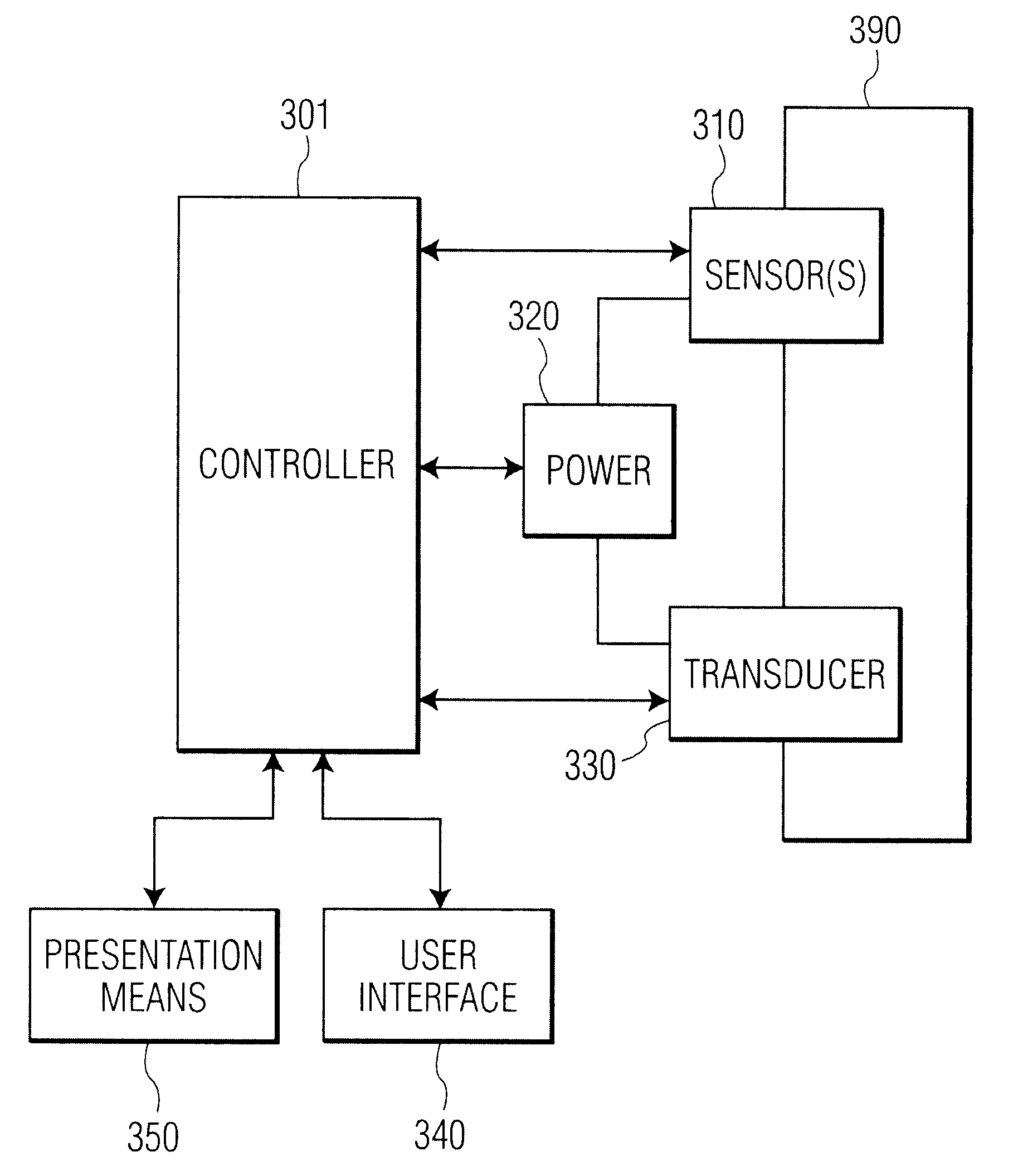
The present invention is directed to a novel system and method of controlling the radiant heat from the patient contact surface of an ultrasonic transducer. Although the details of implementation may be different in different embodiments, the present invention is not limited to any particular type of ultrasonic transducer, whether used internally or externally, or any particular mode of imaging and / or data analysis. The presently preferred embodiments of the present invention control the temperature of the transducer face by alternating the imaging modes of the system based on feedback from temperature sensing elements placed in the transducer. In one preferred embodiment, the system switches from a higher power imaging mode to a lower power imaging mode when a threshold temperature is reached. In another preferred embodiment, the system switches to a "mixed" imaging mode, where the system cycles between a higher power imaging mode and a lower power imaging mode.

A block diagram of t...


PUM


Abstract

A system and method for controlling the heat of an ultrasonic transducer is disclosed. The presently preferred embodiments of the present invention control the temperature of the transducer face by changing the imaging modes of the system. In a preferred embodiment, feedback from temperature sensing elements placed in the transducer is used to determine when to switch from a higher power imaging mode to a lower power imaging mode. In another preferred embodiment, the system switches from a higher power imaging mode to a lower power imaging mode after a predetermined period of time has elapsed. In yet another preferred embodiment, the system switches to a "mixed" imaging mode, where the system cycles rapidly between a higher power imaging mode and a lower power imaging mode, and the resulting data is combined to form a single image.

Description

1. Field of the InventionThe invention relates generally to the field of imaging ultrasonic medical transducer assemblies, and, specifically, to an apparatus and method for cooling the transducer.2. Description of the Related ArtImaging ultrasonic medical transducers are used to observe the internal organs of a patient. The ultrasonic range is described essentially by its lower limit: 20kHz, roughly the highest frequency a human can hear. The medical transducers emit ultrasonic pulses which echo (i.e., reflect), refract, or are absorbed by structures in the body. The reflected echoes are received by the transducer and these received signals are translated into images. Such translation is possible because the reflections from the internal organs vary in intensity according to the "acoustic impedance" between adjacent structures. The acoustic impedance of a tissue is related to its density; the greater the difference in acoustic impedance between two adjacent tissues the more reflecti...

Claims


Application Information

Patent Timeline
Patent Type & Authority Patents(United States)
IPC IPC(8): A61B8/00
CPCA61B8/00A61B8/546A61B8/5238A61B8/467
Inventor MILLER, DAVIDSALGO, IVANPESZYNSKI, MICHAEL
Owner KONINKLIJKE PHILIPS ELECTRONICS NV
Why Eureka
Try Eureka