
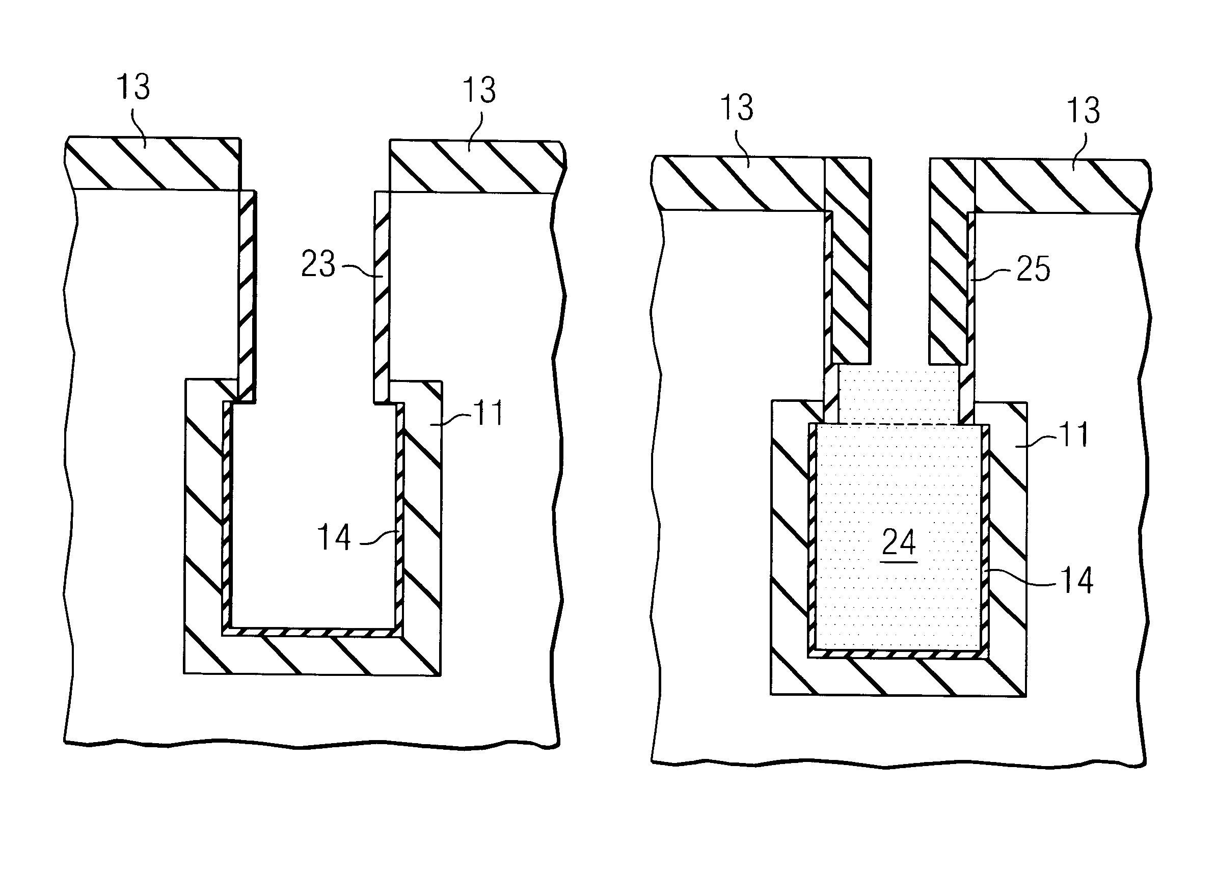
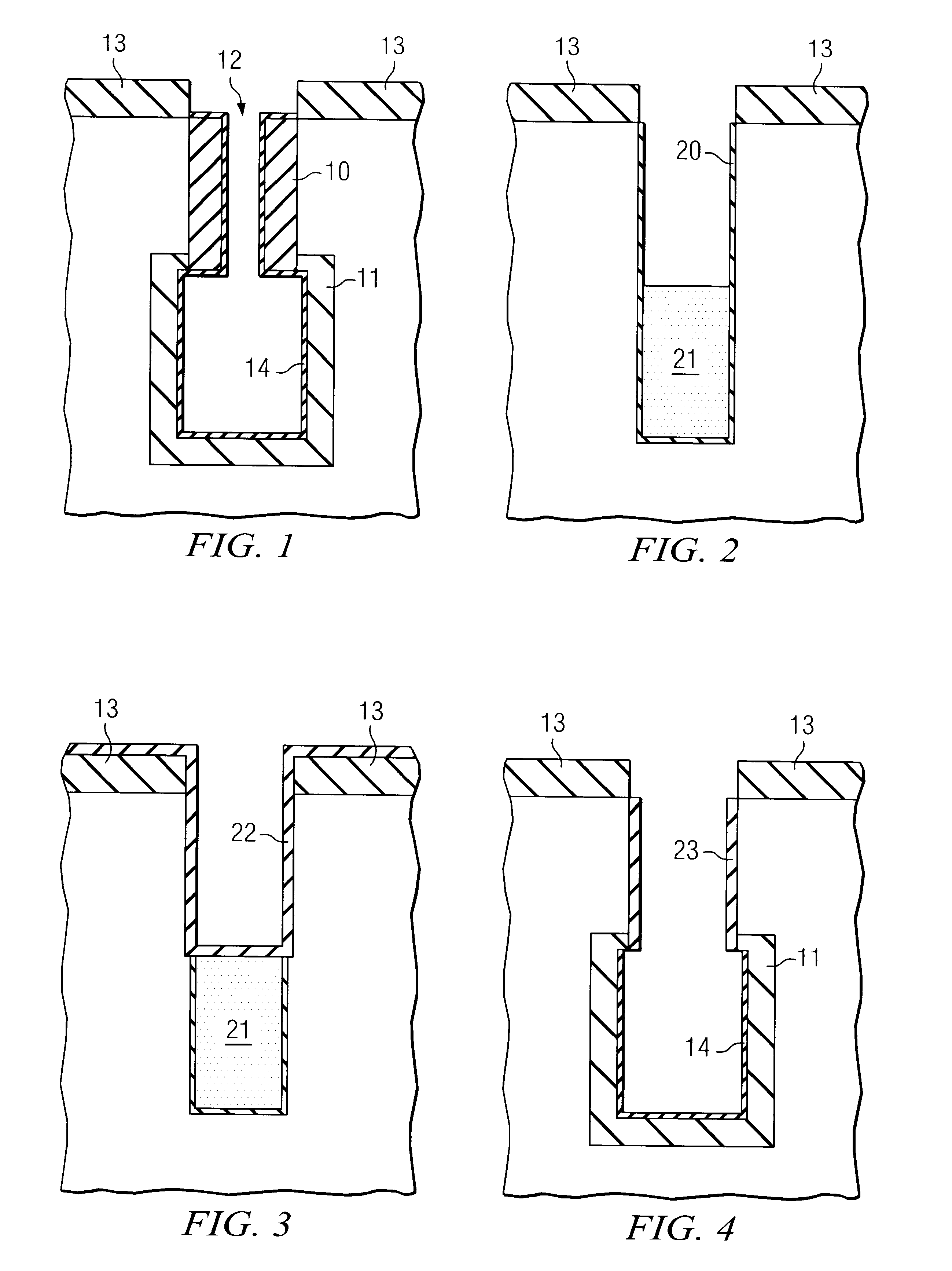
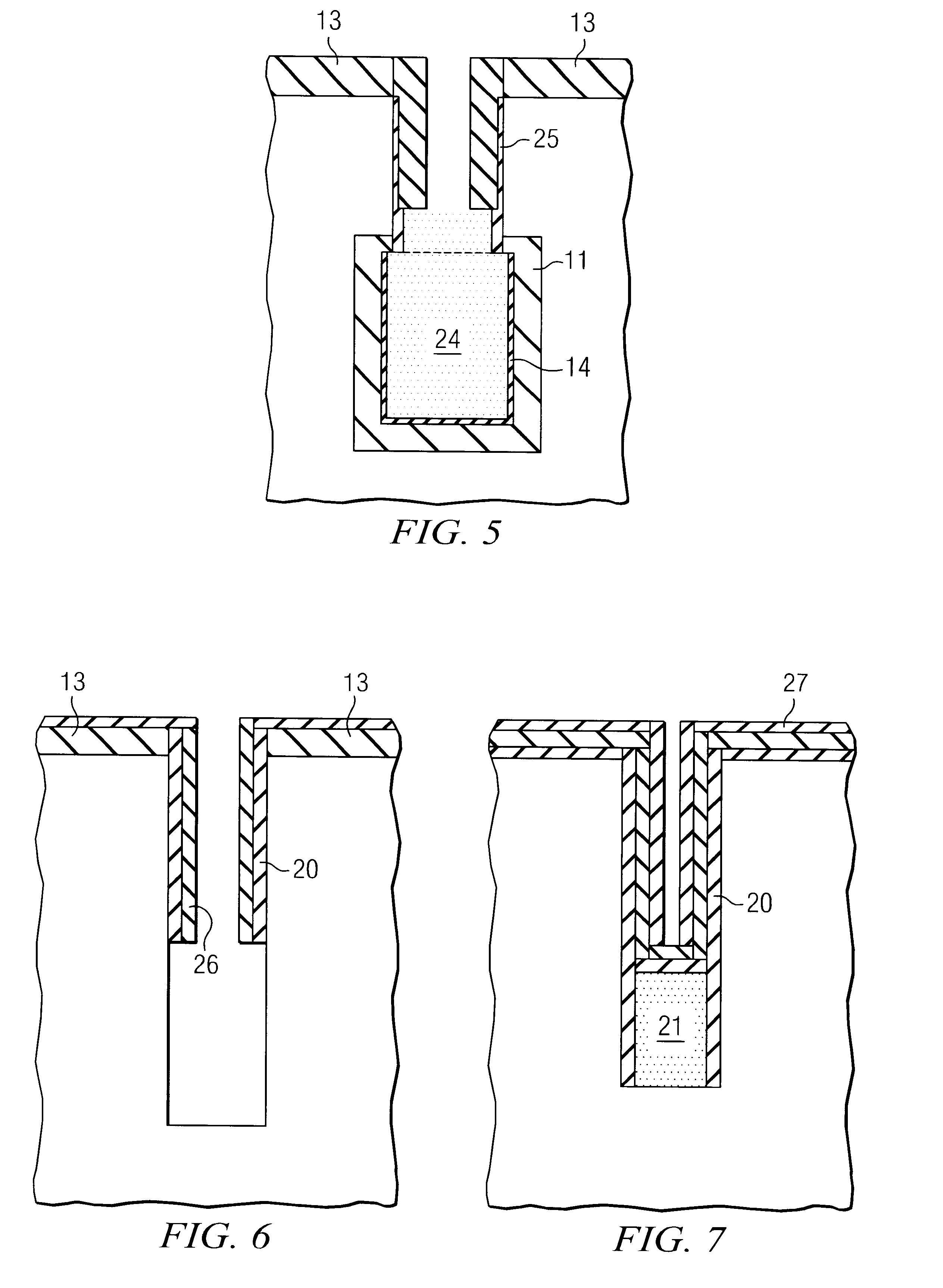
Process flow for two-step collar in DRAM preparation

a dram and process flow technology, applied in the field of dynamic random access memories, can solve the problems of not being able to use trench bottle process or self-aligning formation, the process step of forming the buried strap formation complicates the deep trench process, and it is extremely difficult to execute all dt process steps after the collar formation

Inactive Publication Date: 2003-12-30
POLARIS INNOVATIONS
View PDF7 Cites 17 Cited by
  • Summary
  • Abstract
  • Description
  • Claims
  • Application Information

AI Technical Summary

Benefits of technology

Another object of the present invention is to provide a process for eliminating the very small opening of a DRAM trench in the usual trench DRAM processing for small ground rules, in which the small opening has been further reduced by the formation of an isolation collar on the trench sidewalls.
A further object of the present invention is to provide a process for eliminating the very small opening of a DRAM trench in usual trench DRAM processing for small ground rules, in which the small opening has been further reduced by the formation of an isolation collar on the trench sidewalls, wherein it is extremely difficult to execute all DT process steps after collar formation until the DT fill.

Problems solved by technology

The process step of forming the buried strap formation complicates the deep trench process.
If the collar formation is done after the formation of the storage capacitor in the bottom part of the trench, it is not possible to use techniques like trench bottle process or self aligned formation of a buried plate.
It is therefore extremely difficult to execute all DT process steps after collar formation.
In addition, the thickness of the polysilicon layer in the trench acting as inner electrode of the storage capacitor is extremely thin.

Method used


Image

  • Process flow for two-step collar in DRAM preparation
  • Process flow for two-step collar in DRAM preparation
  • Process flow for two-step collar in DRAM preparation

Examples


Embodiment Construction

The present invention describes a process for making a DRAM in which the process results in a full trench opening during trench processing. This full trench opening is especially important when node dielectrics with high dielectric constants are used. These collar layers that result from fuller trench openings allow the use of larger node thicknesses, i.e. 1.5 to 4 fold dielectric thicknesses for the same oxide equivalent thickness.

For example, when considering the capacity of a system consisting of two conducting plates and a dielectric in between, it is governed by the formula: ##EQU1##

Where Cox is the capacity per unit area, c is the dielectric constant, and tox is the thickness of the dielectric layer. Doubling the dielectric constant allows a doubling of the thickness of the layer to obtain the same capacity as previously. The advantage of a larger thickness is the benefit of a low leakage current.

In the context of the invention, a material with a high dielectric constant will ...


PUM


Abstract

In a method of forming a DRAM cell in a semiconductor substrate, the improvement of maintaining a substantially full trench opening during trench processing comprising: a) forming a pad nitride on the surface of the substrate and reactive ion etching (RIE) a trench vertically to a first depth; b) depositing a nitride layer in the trench; c) filling the trench with a poly silicon fill; d) recess etching the fill to the collar depth; e) oxidizing to transform the exposed nitride layer into a nitrided oxide collar or depositing an oxide on the layer of nitride; f) reactive ion etching to open the bottom oxide; g) stripping the poly fill trench, and performing a nitride etch selective to oxide; h) expanding the trench horizontally by etching lower trench sidewalls and bottom while masking the upper sidewalls; i) forming a buried plate at the bottom of the trench sidewalls; j) forming the node dielectric in the deep trench to grow a collar oxide that consists of a nitrided oxide and a layer of node nitride; k) filling the trench with a poly fill; l) recess etching the poly fill approximately to the collar bottom; m) depositing a collar oxide; n) reactive ion etching to open the bottom; o) filling the trench with a poly fill; and p) chemically mechanically polishing the semiconductor substrate.

Description

1. Field of the InventionThe invention relates to Dynamic Random Access Memories (DRAMS), and more particularly to improvement in the process of preparing DRAMS to overcome the small opening of a DRAM trench due to the small ground rules in the formation of an isolation collar on trench sidewalls, by utilizing a process flow which uses a thin dielectric replacement collar for all DT processes until the DT fill, and after a recess, forming the final collar in a second step.2. Description of the Prior ArtDeep trench (DT) based storage devices are used in DRAM cells, and these devices are generally etched from about 4 to 8 microns deep into the silicon substrate. Further, while the process for forming the deep trench differs between 4 Mb up to 1GB DRAM cells, nevertheless, there are a certain number of process steps common to each of the five generations of DRAM cells.The commonly used deep trench processing steps, which form a large portion of the cost of making each of these trench-b...

Claims


Application Information

Patent Timeline
IPC IPC(8): H01L21/70H01L21/8242
CPCH01L27/10861H01L27/1087H10B12/0387H10B12/038
Inventor TEWS, HELMUT HORSTKUDELKA, STEPHANGENZ, OLIVER
Owner POLARIS INNOVATIONS
Learn More