Characteristically terminated write driver with compensation for magnetic response and method therefor

a write driver and magnetic response technology, applied in pulse generators, instruments, pulse techniques, etc., can solve the problems of time shift in written data (timing distortion), difficult to increase the characteristic impedance of the ils, and now the reversal time of the write head current reversal time is now

Inactive Publication Date: 2003-12-30
INT BUSINESS MASCH CORP
View PDF10 Cites 18 Cited by
  • Summary
  • Abstract
  • Description
  • Claims
  • Application Information

AI Technical Summary

Problems solved by technology

With these higher data rates, T is becoming so small that the echoes of a previous current reversal may not have dissipated enough at the next current reversal, thereby causing a timing shift in the written data (timing distortion).
The disadvantage of this conventional characteristic source termination scheme is that the achievable write head current reversal time is now determined by the inductance of the write head and the characteristic impedance of the ILS:
However, increasing the characteristic impedance of the ILS is difficult because the width of the traces becomes disappearingly small (for acceptable tolerances in the characteristic impedance of these lines about 80 .OMEGA. seems to be the maximum achievable impedance given the materials and dimensions used) Lowering the head inductance without increasing the write current to excessive levels has shown to be difficult.
Such excessive write currents would require large area transistors in the write driver, associated with larger parasitics.
This would slow down the write driver.

Method used


Image

  • Characteristically terminated write driver with compensation for magnetic response and method therefor
  • Characteristically terminated write driver with compensation for magnetic response and method therefor
  • Characteristically terminated write driver with compensation for magnetic response and method therefor

Examples


Embodiment Construction

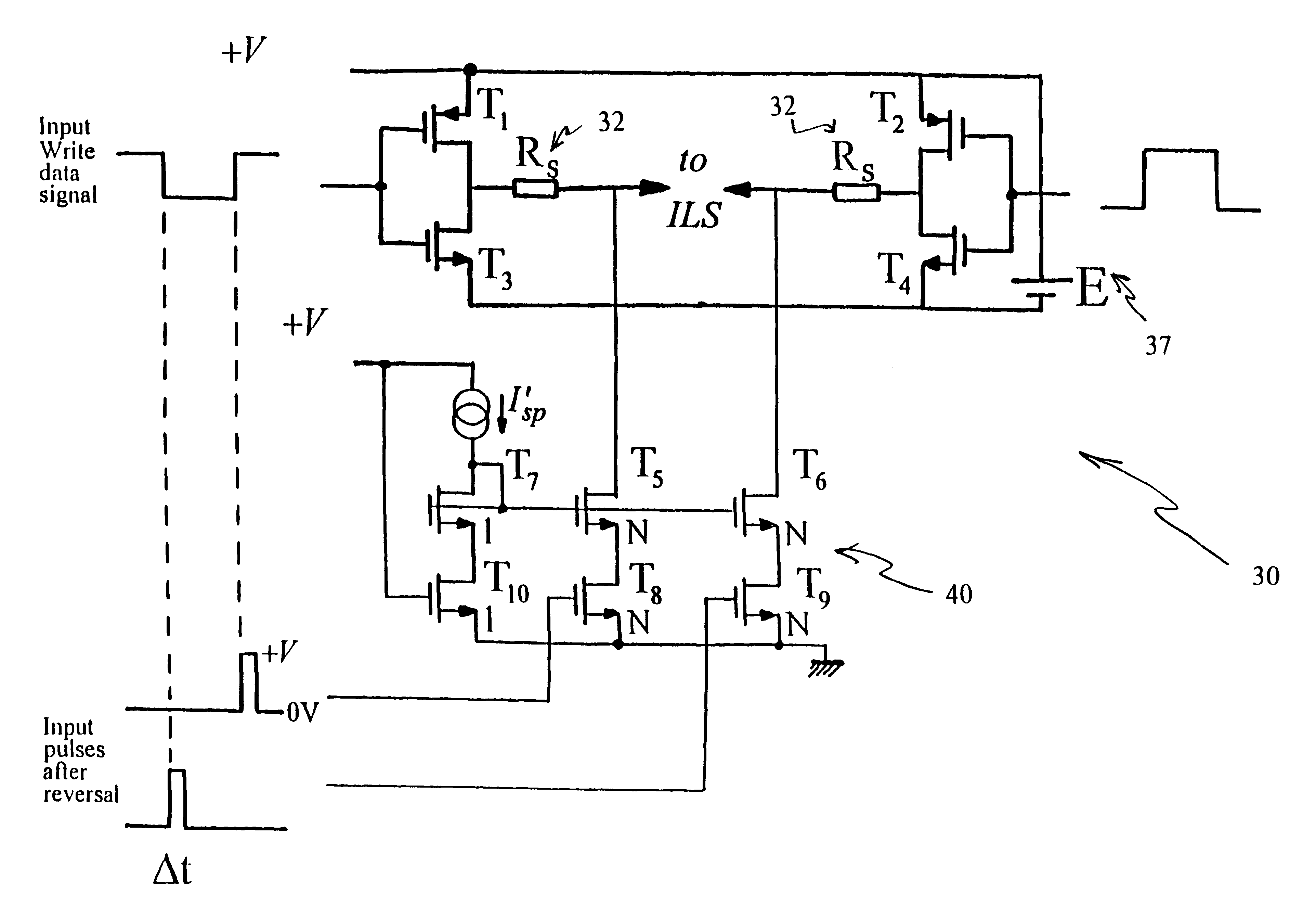
Turning now to the drawings, preferred embodiments of the invention will be described. Generally, the principle of the invention is shown in FIG. 3(a). Similar to conventional write drivers this circuit includes a write driver 30, matching termination impedance 32, an ILS 34, and write head 36. FIG. 3(a) shows a source-terminated voltage-type write driver 30 where during each input write data signal reversal the write driver output terminals are temporarily connected between the top and bottom power supply lines (in this example between+V and GND) by transistor switch pair T.sub.2,T.sub.5 or T.sub.1,T.sub.6, depending on the data polarity. This applies the full supply voltage V at the output of the driver 30 and provides the maximum possible write driver source strength enhancement without adding costly circuitry components such as voltage doublers. Note that the additional voltage above normal write voltage 37 is provided by turning on one of either transistor pair T.sub.5,T.sub.6 ...


PUM

PropertyMeasurementUnit
lengthaaaaaaaaaa
lengthaaaaaaaaaa
widthaaaaaaaaaa

Abstract

A method (and magnetic recording circuit structure) for write drivers to reduce the reversal time for the current through the inductive recording head, includes a write driver output stage providing a write signal output with a write signal source strength SO, a magnetic write head with a write signal input essentially equal to strength SO, and an interconnect circuit having a characteristic impedance ZO coupled to the write signal output of the write driver output stage and the magnetic write head. The write driver output stage preferably includes a source-side termination circuit having output impedance ZS, wherein the source-side termination circuit output impedance ZS is substantially equal to ZO and the source strength SO of the write driver at the input of the interconnect circuit is temporarily enlarged after every polarity reversal of the write signal for a predetermined time duration Deltat.

Description

1. Field of the InventionThe present invention generally relates to a technique of using an inductive recording head to store information onto a magnetic medium, and in particular to circuits for reducing the current reversal time of the current through the inductive recording head for write drivers having an H-type configuration.2. Description of the Related ArtTypically, a conventional H-type current write driver drives a magnetic recording head via a suspension interconnect. Because of the relatively low data rates, the current reversal times in the magnetic recording head are relatively large with respect to the echo-return time (e.g., twice the "time of flight" of the interconnect) which, for an industry standard interconnect in a 3.5 inch drive has a length of 5 cm, is approximately 500 picoseconds. As a result, when the next current reversal arrives at the head, the echoes of the previous current reversal have dissipated enough not to cause a noticeable transition shift in th...

Claims


Application Information

Patent Timeline
Patent Type & Authority Patents(United States)
IPC IPC(8): G11B5/02G11B5/00
CPCG11B5/02G11B5/022G11B2005/0013
Inventor KLAASSEN, KLAAS BERENDVAN PEPPEN, JACOBUS CORNELIS LEONARDUS
Owner INT BUSINESS MASCH CORP
Why Eureka
Try Eureka