Antiglare optical device

an optical device and antiglare technology, applied in the direction of roofs, instruments, lighting and heating apparatuses, etc., can solve the problems of inability to filter, inability to drive, accidents, etc., and achieve the effect of preventing impairment of vision and not reducing the filter

Inactive Publication Date: 2004-01-06
COUNCIL OF SCI & IND RES
View PDF5 Cites 22 Cited by
  • Summary
  • Abstract
  • Description
  • Claims
  • Application Information

AI Technical Summary

Benefits of technology

Still another object of the present invention is to provide a method for the preparation of an antiglare optical device for protecting the eyes of the automobile driver during night driving.
Yet another object of the present invention is to provide a method for the preparation of an antiglare device to protect the automobile drivers eye from radiation in the wavelength range 320-400 nm and 750-1400 nm.
One more object of the present invention is to prevent impairment of vision due to development of cataract in the crystalline lens by the UV radiation and also retinal deterioration caused due to the thermal effects of IR radiation in the long run.
The present invention relates to a method of deposition of an absorbing material upon a plastic / glass substrate by vacuum coating at an angle of inclination between 5.degree. to 30.degree. and using a mask on the evaporation source to produce a graded film material. More particularly, the present invention relates to a method for the preparation of graded density absorbing film useful as an antiglare optical device for protecting the eyes by reducing the glare by absorbing the light intensity falling upon it on a non-uniform fashion.
In another embodiment of the present invention, the RHS of the device seen in the direction of view of the driver blocks the blinding glare coupled with attenuation in the wavelengths regions 320-400 nm in the UV and 750-1400 nm in the IR, at the same time visualisation of the road from the center as well as LHS of the filter is not reduced.
In still another embodiment of the present invention, the said article protects the driver's eye from the radiation in the wavelength range 320-400 nm and 750-1400 nm produced by the headlights of approaching vehicles in order to prevent impairment of the vision due to development of cataract in the crystalline lens by the UV radiation and also retinal deterioration caused due to the thermal effects of IR radiation in the long run.

Problems solved by technology

The necessity of Night driving filter was felt as in the night time It becomes very difficult to drive on the high ways due to the radiations falling on the eye of incoming vehicles on the driver's eye.
The excessive radiations falling on the eye makes the eye pupil to close resulting in the darkness of the view in front of the driver and accidents occur.
Also the UV and IR content of the radiations make the eyes prone to cataract and other diseases.
These radiations blind the driver due to which a number of accidents occur in the night.
The frequent blinding glare not only makes the driving difficult, but also impairs the vision.
The impairment of the vision occurs due to development of cataract in the crystalline lens by the UV radiation and also retinal deterioration caused due to the thermal effects of IR radiation in the long run.
However, the literature of the product does not give any spectral curve or technical clarifications justifying the use of spectacle glasses for night driving.

Method used


Image

  • Antiglare optical device
  • Antiglare optical device
  • Antiglare optical device

Examples


example 1

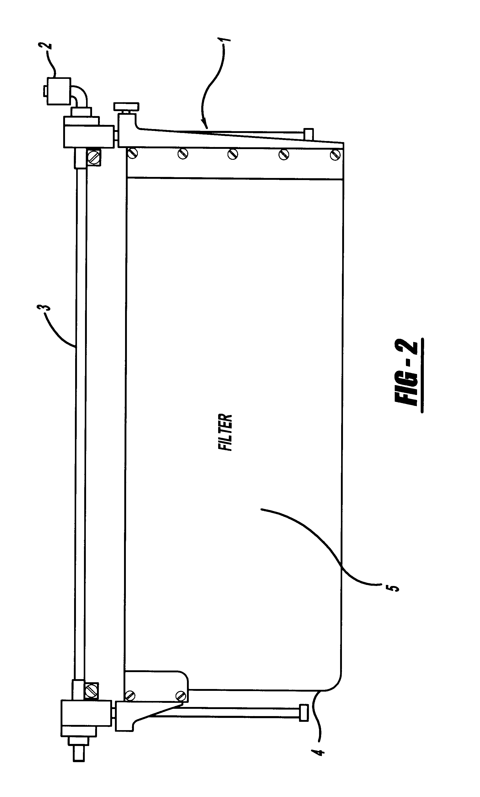
Accordingly the present invention provides an improved antiglare optical device for automobiles useful during night driving; to be mounted in front of the driver on the automobile's wind shield which comprises of a gradient density absorbing film deposited upon glass / plastic substrate by vacuum coating and also Anti-Reflection (AR) coating on both surfaces of the substrate, providing adjustments on the wind shield for the compensation in the drivers eye-level and also providing means to latch on to the automobile's ceiling when not in use, clearing the steering wheel and the driver's head.

The provisional specifications of the filter are:

Substrate Material: Optical glass, Polycarbonate plastic.

Size: 300.times.150.times.2-3 mm duly mounted inmechanical frame for fitment in the car.

Coating:

Glass Substrate: Graded absorbing film over coated with AR film on one surface and only AR film on second surface.

Plastic Substrate: Graded absorbing film over coated with AR film on one surface and ...

example 2

Computation of Thickness Gradation

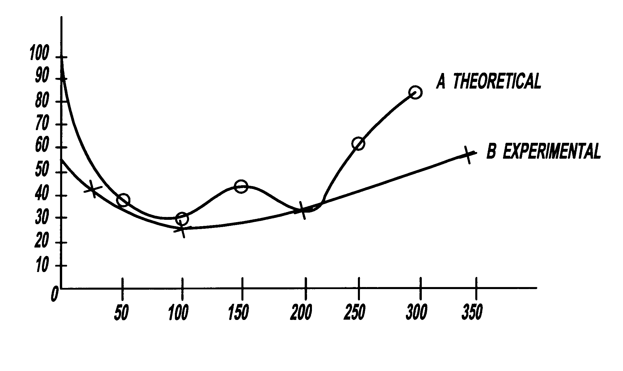
The film gradation is designed by taking into consideration the luminance distribution of light on the wind shield from the approaching vehicle, distance between the two vehicles and the distance of the filter from the center of rotation of the cyc. In this connection, the necessary data has been generated by conducting the requisite experiments. From this data of luminance distribution the thickness gradation of the film in terms of transmission is found for getting gradient density absorbing film. The required gradation profile is given in FIG. 3.

example 3

Experimental Methods

The glass / plastic substrate after proper cleaning ins placed inside the chamber of a vacuum coating plant in an inclined position with respect to evaporation source. The angle of inclination varies from 5.degree. to 30.degree.. Tungsten spiral filament is used as the source for the evaporation of absorbing material and a mask is suitably positioned above the filament; the chamber is then evacuated to a high vacuum. After achieving the vacuum better than 2.times.10.sup.-5 mb, the material is evaporated by passing the current in the filament to obtain the graded absorbing film on the substrate. Afterwards, AR film is deposited on both surfaces by suitably placing the substrate in the chamber. FIG. 3 depicts the gradation profile of the experimental coating without having AR coating on both surfaces. The data for the profile was obtained by measuring the transmission at 550 nm on various locations of the filter. It can be seen from the figure that at a distance of 1...


PUM

PropertyMeasurementUnit
wave lengthaaaaaaaaaa
wavelength regionaaaaaaaaaa

Abstract

The present invention relates to a method of deposition of an absorbing material upon a plastic / glass substrate by vacuum coating at an angle of inclination between 5° to 30° and using a mask on the evaporation source to produce a graded film material and a method for the preparation of graded density absorbing film useful as an antiglare optical device for protecting the eyes by reducing the glare by absorbing the light intensity falling upon it in a non-uniform fashion.

Description

The present invention relates to a method of deposition of an absorbing material upon a plastic / glass substrate by vacuum coating at an angle of inclination between 5.degree. to 30.degree. and using a mask on the evaporation source to produce a graded film material. More particularly, the present invention relates to a method for the preparation of graded density absorbing film useful as an antiglare optical device for protecting the eyes by reducing the glare by absorbing the light intensity falling upon it in a non-uniform fashion.BACKGROUND AND PRIOR ART TO THE INVENTIONThe necessity of Night driving filter was felt as in the night time It becomes very difficult to drive on the high ways due to the radiations falling on the eye of incoming vehicles on the driver's eye. The excessive radiations falling on the eye makes the eye pupil to close resulting in the darkness of the view in front of the driver and accidents occur. Also the UV and IR content of the radiations make the eyes ...

Claims


Application Information

Patent Timeline
Patent Type & Authority Patents(United States)
IPC IPC(8): C03C17/36C23C14/06C23C14/04C23C14/22
CPCC03C17/36C03C17/3605C03C17/3615C03C17/3621C03C17/3649C03C17/3657C03C17/3681C03C17/3694C23C14/044C23C14/06C23C14/225C03C2218/365
Inventor CHHABRA, DEEP SINGHRAO, PARINAM KRISNASHARMA, BIPIN DEVDODD, DHARAMBIR SINGHSINGH, VIRENDERSHARMA, SANJAY
Owner COUNCIL OF SCI & IND RES
Why Eureka
Try Eureka