Apparatus for sputter deposition

a technology of sputter and apparatus, which is applied in the direction of electrolysis components, vacuum evaporation coatings, coatings, etc., can solve the problems of reducing the quality of the film deposited by the apparatus shown in fig. 1, other hardware and contributing to the contamination of the deposited film, and the material out of which the aperture is formed becomes a source of extraneous sputtering and contamination, so as to reduce the gas load for pumping and reduce the effect o

Inactive Publication Date: 2004-01-27
VEECO INSTR +1
View PDF7 Cites 6 Cited by
  • Summary
  • Abstract
  • Description
  • Claims
  • Application Information

AI Technical Summary

Benefits of technology

In using a compact gridless ion source, the high pressure required for generating ions is confined to the ion source and the gas load for pumping is reduced. For ion energies at or near the sputtering threshold, the sputtering from extraneous hardware is reduced or eliminated. In addition, the target biases can be low enough to minimize the damage due to energetic neutrals that result from the reflection of energetic ions striking the target.

Problems solved by technology

The quality of the film deposited by the apparatus shown in FIG. 1 is limited by the inclusion of contaminants or damage sites in that film.
The neutral efflux, however, results in the need for a neutral density to sustain the electrical discharge that makes the ions.
Even in the most well-defined beam from a gridded ion source of this general type, there are fringe ions that strike other hardware and contribute to contamination of the deposited film.
In that case, the material out of which the aperture is formed becomes a source of extraneous sputtering and contamination.
The fringe beam 26 thus constitutes a serious contamination problem.
These damage sites are caused by the collisions of energetic neutrals 38 with the deposited film and can cause either disruptions of the film or mixing of the film with the substrate.
The obstacle to using low ion energies and low beam voltages in gridded sources is in the space-charge limit of the ion optics used.
While there are some variations in grid design and operating conditions that can be used, the ion beam current capacity of gridded ion optics is severely limited at low beam voltages.
Unfortunately, it is more difficult to control the trajectories of ions in gridless ion sources and the fringe beam 26 in FIG. 1 is a much more serious problem when the ion source 20 is of the gridless type.
The use of a gridless ion source is thus seen to be beneficial in obtaining useful ion beam currents at low ion energies, but to be detrimental in having more ions in the fringe beam 26.
Further, the ion trajectories are strongly affected by the potential distribution within the plasma at these low ion energies, resulting in poorly defined ion trajectories.

Method used


Image

  • Apparatus for sputter deposition
  • Apparatus for sputter deposition
  • Apparatus for sputter deposition

Examples


specific example

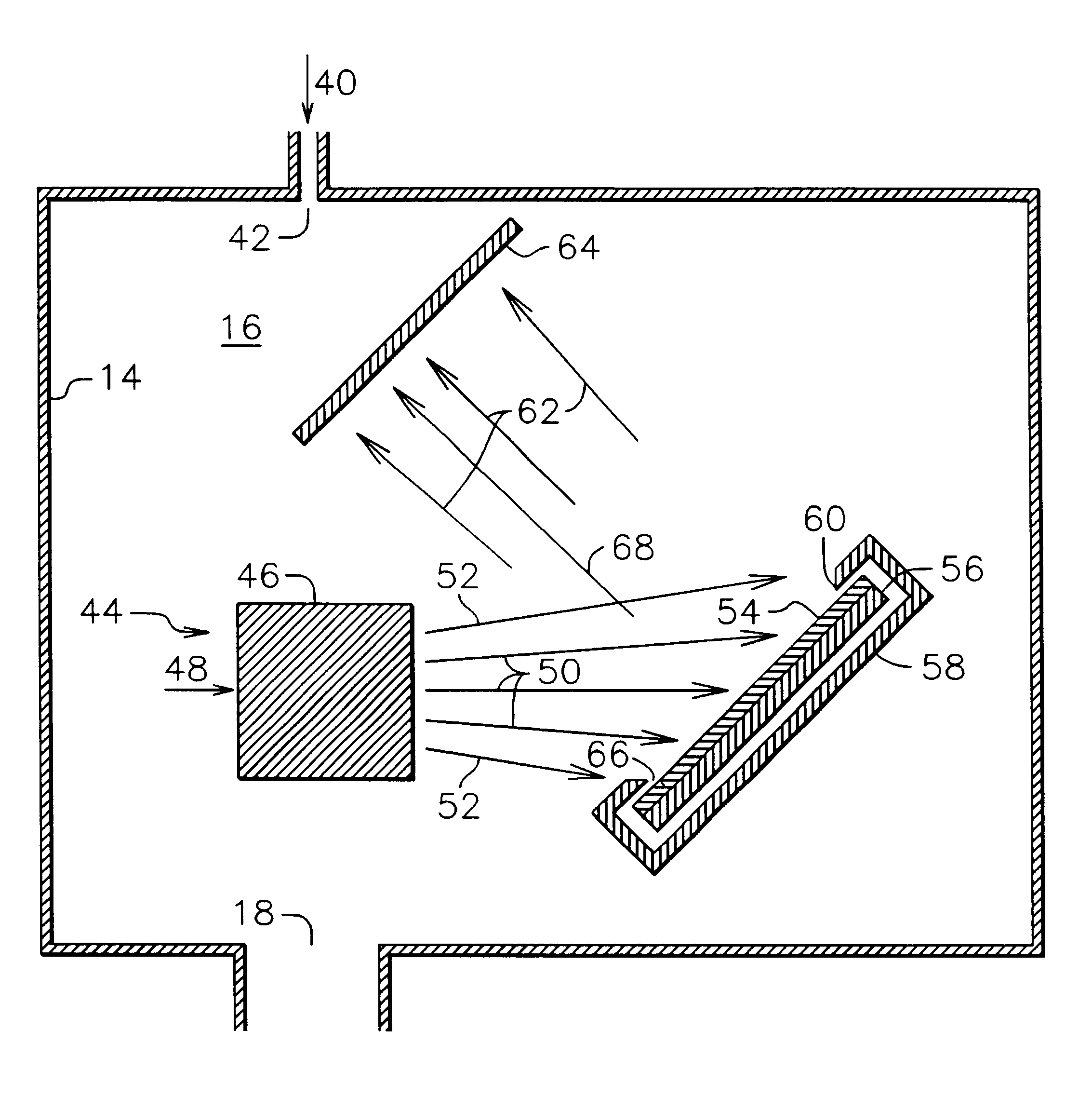
As a specific example of operation, a configuration similar to that shown in FIG. 4 was operated with a commercial end-Hall ion source constructed in accord with U.S. Pat. No. 4,862,032-Kaufman, et al., commercially available as Mark I from Commonwealth Scientific Corporation, Alexandria, Va. This ion source had an external diameter of 64 mm and an overall length including cathode of 106 mm. The target diameter was 95 mm. The extension of the centerline of the ion source passed through the center of the target and had an incidence angle of 45 degrees with that target, approximately as shown in FIG. 4. The ion source was spaced 80 mm from the center of the target. The discharge current of the ion source was 1.0 ampere at a discharge voltage of 38 volts and an argon gas flow of 11 sccm (standard cubic centimeters per minute). The mean ion energy at that discharge voltage was estimated at 20-25 eV. The low discharge voltage was achieved with an electron emission from the cathode of 2.8...


PUM

PropertyMeasurementUnit
energyaaaaaaaaaa
pressureaaaaaaaaaa
energyaaaaaaaaaa

Abstract

In accordance with one specific embodiment of the present invention, the apparatus for sputter deposition within an evacuated volume comprises a compact ion source to generate ions into which an ionizable gas is introduced and from which ions leave with directed energies near or below the sputtering threshold, a sputter target near that source and located within the beam of ions leaving that source, a sputter target with a grounded shield that defines the target portion exposed to sputtering, and a power supply to bias the target negative relative to ground so that ions are attracted to and sputter the target. Particles sputtered from the target are deposited on a deposition substrate separate from both the ion source and the sputter target. For an insulating target, the target is biased with a radiofrequency power supply and the bias has a mean negative value rather than a direct-current negative value relative to ground. The rate and energy with which the ions arrive at the target determine the rate with which that target is sputtered and the deposition rate on the substrate. In using a compact gridless ion source, the high pressure required for generating ions is confined to the ion source, reducing the pumping gas load. For ion energies at or near the sputtering threshold, the sputtering from extraneous hardware is reduced or eliminated. In addition, the target biases can be low enough to minimize the damage due to energetic neutrals that result from reflection of energetic target ions.

Description

This invention relates generally to the deposition of thin films, and more particularly to the deposition of thin films with low contamination by extraneous materials and low damage due to bombardment by energetic ions or neutrals.This invention can find application in a variety of thin film applications such as the deposition of decorative or protective films, the deposition of conducting films for solid state electronics, or the deposition of magnetic films for recording heads or recording media.Sputter deposition is widely used for the deposition of thin films. The most closely related prior art is the sputter deposition from a target that results from an energetic beam of ions being directed against that target. The most widely used ion source for such an application is the gridded ion source described in an article by Kaufman, et al., in the AIAA Journal, Vol. 20 (1982), beginning on page 745, incorporated herein by reference. Although it would be less likely, a gridless ion so...

Claims


Application Information

Patent Timeline
Patent Type & Authority Patents(United States)
IPC IPC(8): C23C14/46H01J37/34H01J37/317H01J37/32C23C14/34
CPCC23C14/46H01J37/3178H01J37/34H01J2237/3146
Inventor KAHN, JAMES R.KAUFMAN, HAROLD R.ZHURIN, VIACHESLAV V.BALDWIN, DAVID A.HYLTON, TODD L.
Owner VEECO INSTR
Why Eureka
Try Eureka