Imaging system with low sensitivity to variation in scene illumination

a technology of scene illumination and image sensitivity, which is applied in the field of image sensitivity, can solve the problems of large amount of information loss, slow response time, and loss of scene detail

Inactive Publication Date: 2004-01-27
FLIR SYSTEMS TRADING BELGIUM BVBA
View PDF13 Cites 65 Cited by
  • Summary
  • Abstract
  • Description
  • Claims
  • Application Information

AI Technical Summary

Problems solved by technology

Electronic sensors such as charge coupled device sensors generally operate over a limited range of illumination levels.
Where there is a bright light source within a scene, the automatic gain control results in the loss of detail in the scene.
Large amounts of information are therefore lost.
The structure had a slow response time and so was limited to bright scenes and mismatch between devices meant that only objects with a relatively high contra

Method used


Image

  • Imaging system with low sensitivity to variation in scene illumination
  • Imaging system with low sensitivity to variation in scene illumination
  • Imaging system with low sensitivity to variation in scene illumination

Examples


Embodiment Construction

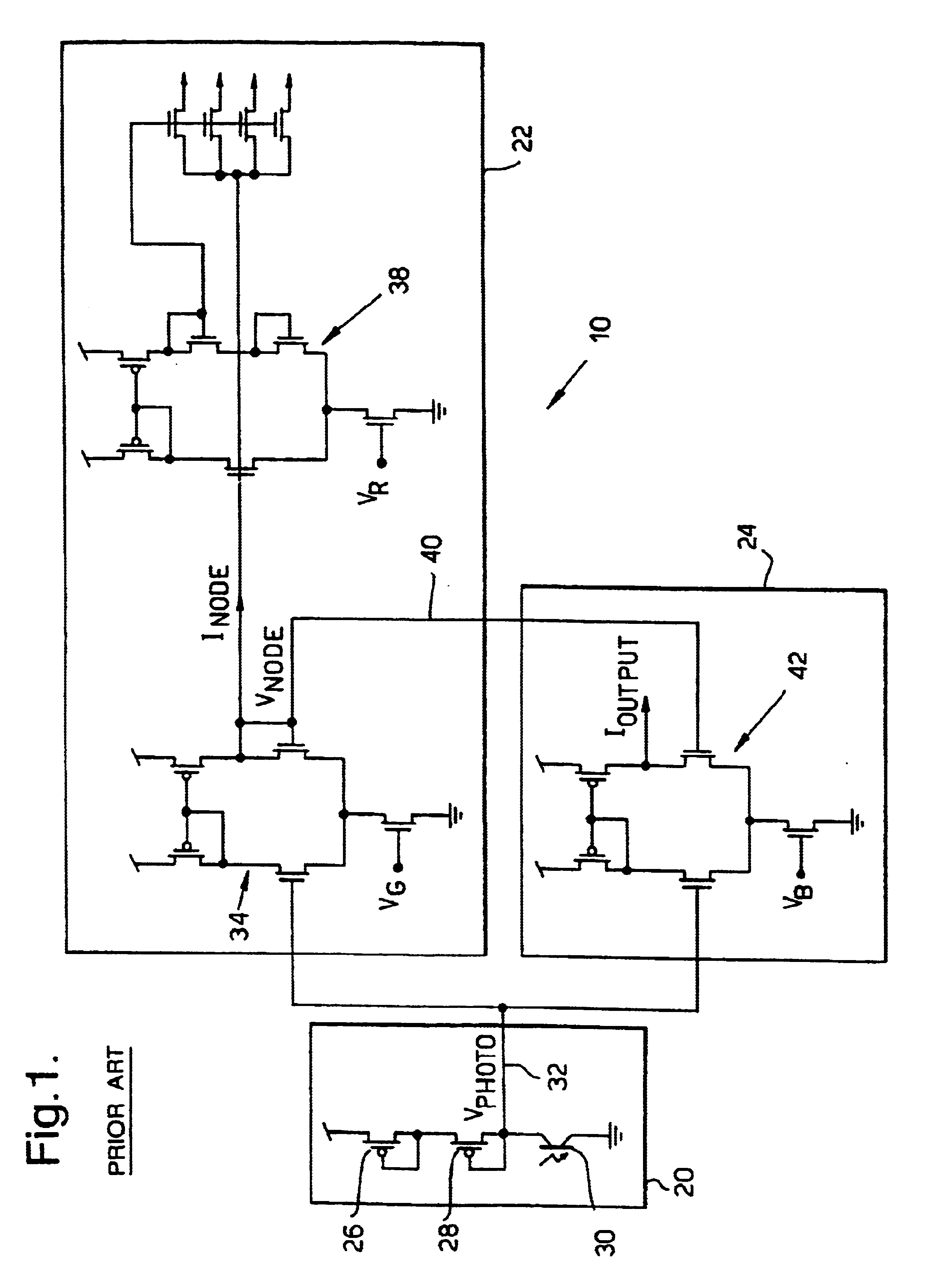
Referring to FIG. 1 there is shown a circuit diagram of a single pixel 10 of a prior art silicon retina developed by Mead referred to earlier. The pixel 10 comprises a receptor unit 20, a lateral averaging unit 22 and an output unit 24. The receptor unit 20 is a logarithmic detector comprising two diode connected channel metal oxide semiconductor field effect transistors (MOSFETs) 26 and 28 and a p-n-p phototransistor 30. An output 32 from the detector unit 20 is connected to both the lateral averaging unit 22 and the output unit 24.

The lateral averaging unit 22 comprises a transconductance amplifier 34. The unit 22 calculates a local average response using a network of lateral connections 36 to adjacent pixels. The amount of current injected into the network within each pixel through the transconductance amplifier 34 is dependent upon the difference between the voltage of the network, V.sub.Node and the output voltage of the receptor unit 20, V.sub.photo, thereby creating a weighte...


PUM


Abstract

An imaging system comprises an image detection unit (52) and a filter unit (58). Pixel image signals are passed in parallel from the image detection unit (52) to the filter unit (58). Circuit elements within each pixel (56) generate pixel image signal whose amplitude is proportional to the logarithm of the image intensity at that pixel. The filter unit (58) carries out a spatial filtering operation and outputs the result.

Description

This application is the US national phase of International Application No. PCT / GB95 / 02808, filed Dec. 1, 1995, the entire content of which is hereby incorporated by reference.1. Field of the InventionThe present invention relates to an imaging system.2. Discussion of Prior ArtIn order for a mammalian eye to be able to observe objects over a wide range of light intensity levels, a mammalian retina comprises five general types of neurons organised into a two layer system. A first layer, the outer plexiform layer, consists of detector, horizontal and bipolar neurons. It has been shown that the detector neurons' response is a logarithmic function of the photon flux. Signals from the detector neurons are passed to the horizontal neurons which allow the signals to spread laterally. The bipolar neurons respond to the differences between the signals from the detector and horizontal neurons. The result is a bipolar neuron response which is a function of the spatial and temporal changes in th...

Claims


Application Information

Patent Timeline
IPC IPC(8): H04N5/217H04N3/15H04N5/335H04N5/30H01L27/146H04N5/365
CPCH01L27/14603H04N5/335H04N5/3653H04N25/00H04N25/672
Inventor COLLINS, STEPHENMARSHALL, GILLIAN FWADE, MICHAEL F
Owner FLIR SYSTEMS TRADING BELGIUM BVBA
Why Eureka
Try Eureka