Electrical power conservation apparatus and method

a technology of electric power conservation and power saving equipment, applied in the field of ac electrical power, can solve the problems of affecting the efficiency of ac-ac conversion, and causing havo

Inactive Publication Date: 2004-02-10
MICROPULSE TECH
View PDF20 Cites 42 Cited by
  • Summary
  • Abstract
  • Description
  • Claims
  • Application Information

AI Technical Summary

Benefits of technology

FIG. 5 depicts a simple embodiment of the switching means.
FIGS. 6A and 6B show an embodiment of a control means for controlling the timing and duration of current interruptions provided by the switching means and providing the additional ability to monitor and adjust the circuit to the load.

Problems solved by technology

Conventionally used "dimmers" frequently are not actually saving any energy as many simply use a resistor which is placed in the circuit with the light being dimmed to absorb current that would otherwise be available to the light.
The longer the void created in the current cycle, the less current is available to the attached device, however the greater the interruption in the timing and the greater the difference between the output frequency and input frequency.
However, such devices in chopping a single segment from one side of the current cycle play havoc with electrically powered devices which depend upon the continuing and constant oscillation of the current cycle providing a timer to the attached device.
Computers and induction motors and similar devices seeking the constant 60 Hz or 50 Hz cycles of line current are seriously impaired for function when a large portion of one cycle is void of electrical current.
Some devices may even falsely sense that the current is reversing if the segment of current void for a sufficient time increment, thus disabling the device or even causing damage to the circuits when the current restarts.
Another serious problem arises in the use of induction style AC electric motors which are major energy consumers and thus a major target for electrical energy conservation.
This current interruption throws the current frequency out of balance and plays havoc with the fields formed inside the motor by the windings since they are spaced to take advantage of the 60 Hz or 50 Hz frequency in generating the fields around the armature.
Interrupting the current flow in a single segment section during one oscillation collapses the magnetic field during the time that the current is interrupted and either throws the motor out of balance causing erratic rotation, overheating, and eventual failure of the device.
Lengthening the interruption as is conventionally done with light bulb dimmers to lower the output, further increases the damage done to the running of the induction motor by further collapsing the magnetic fields and throwing the device out of balance.
Consequently conventional dimmer style current interruption devices will not function upstream in the power suppled in such a circuit since the subsequent device downstream in the circuit tries to undo the interruption of current which the dimmer chops from one side of the AC oscillation.
Since each complete cycle of a conventional 60 Hz AC circuit used in the United States takes only one second, the duration of each of the twenty-five interruptions on both oscillations is extremely short.
Further, since there are so many short interruptions, lengthening or shortening each interruption varies the effective maximum current available to the circuit widely without causing the devices attached to sense an end to the negative or positive oscillation of the cycle.
However, Smith teaches a constant pulse or current interruption duration and varying the frequency of the line output and requires a power transformer and chokes to accomplish the task.
This makes the device bulky and yields the potential of damage to frequency specific devices such as induction motors and computers.

Method used


Image

  • Electrical power conservation apparatus and method
  • Electrical power conservation apparatus and method
  • Electrical power conservation apparatus and method

Examples


Embodiment Construction

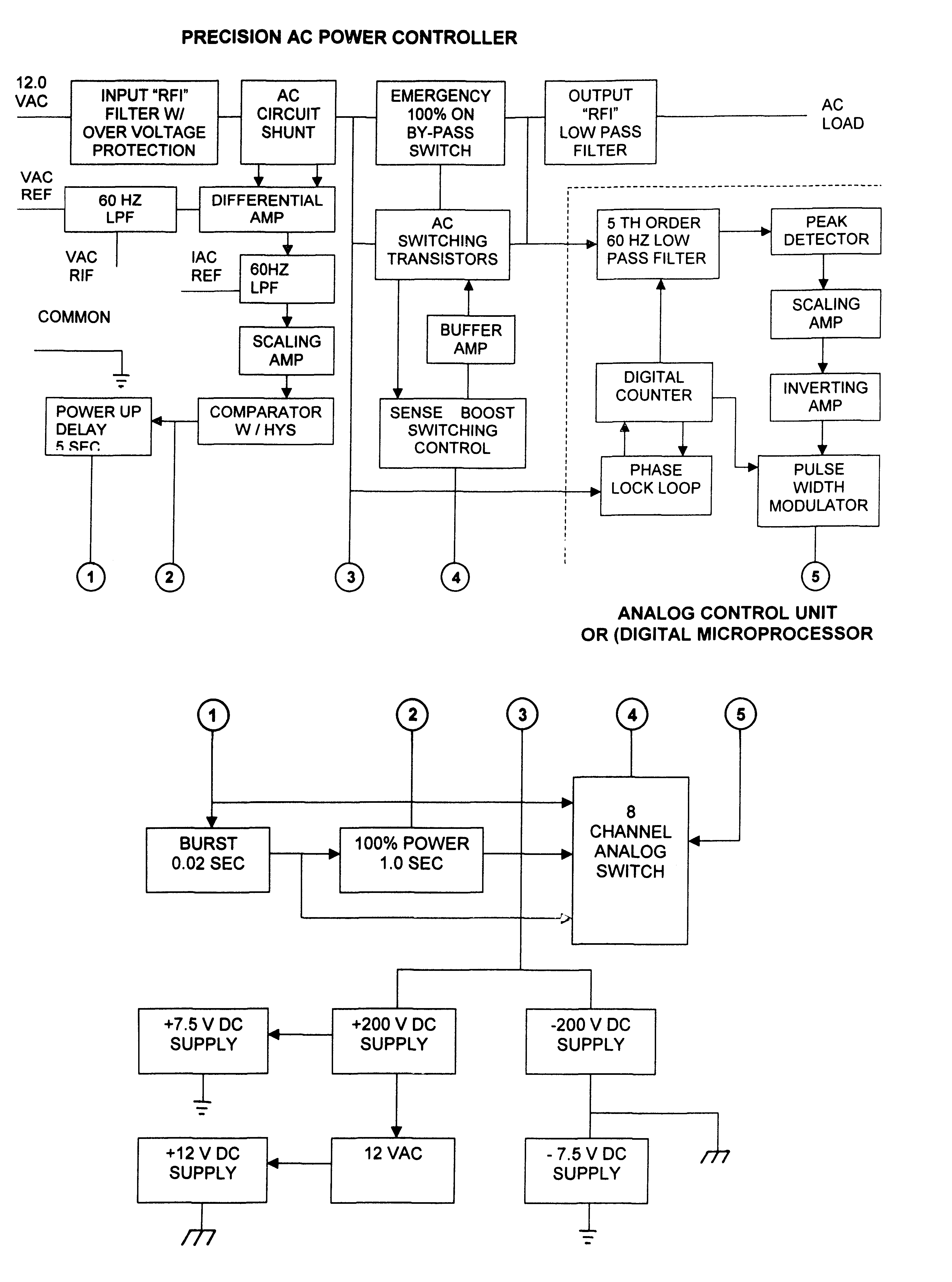
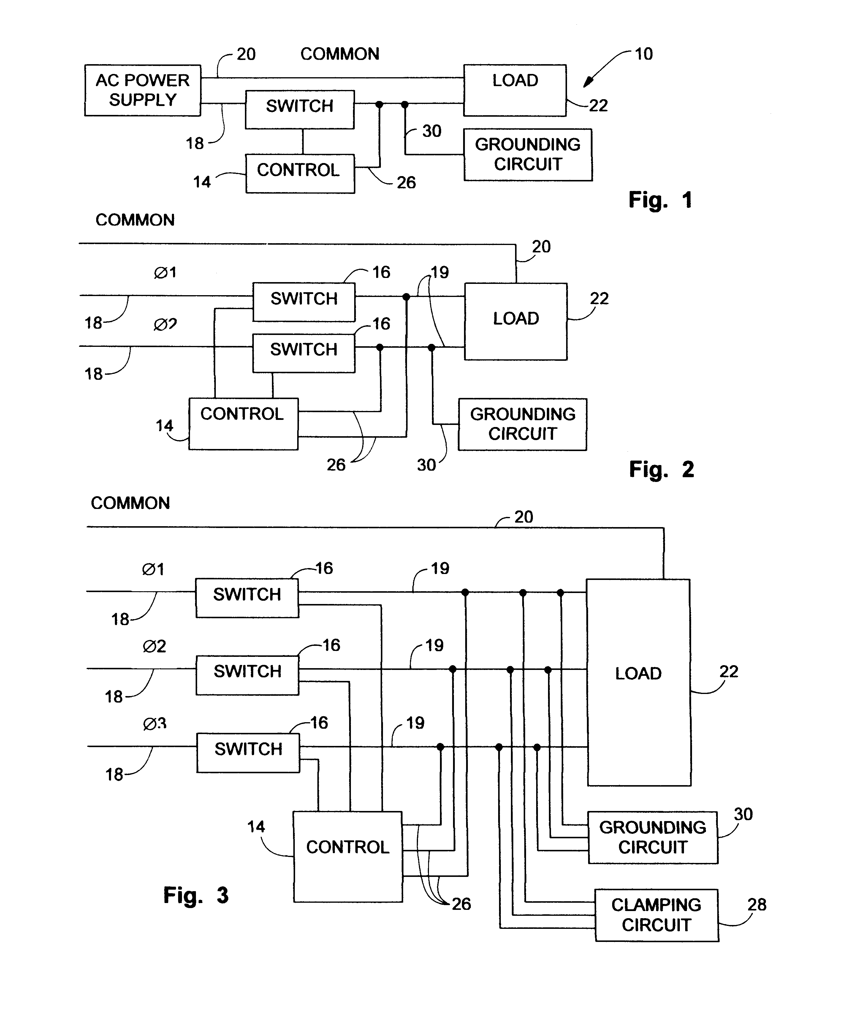
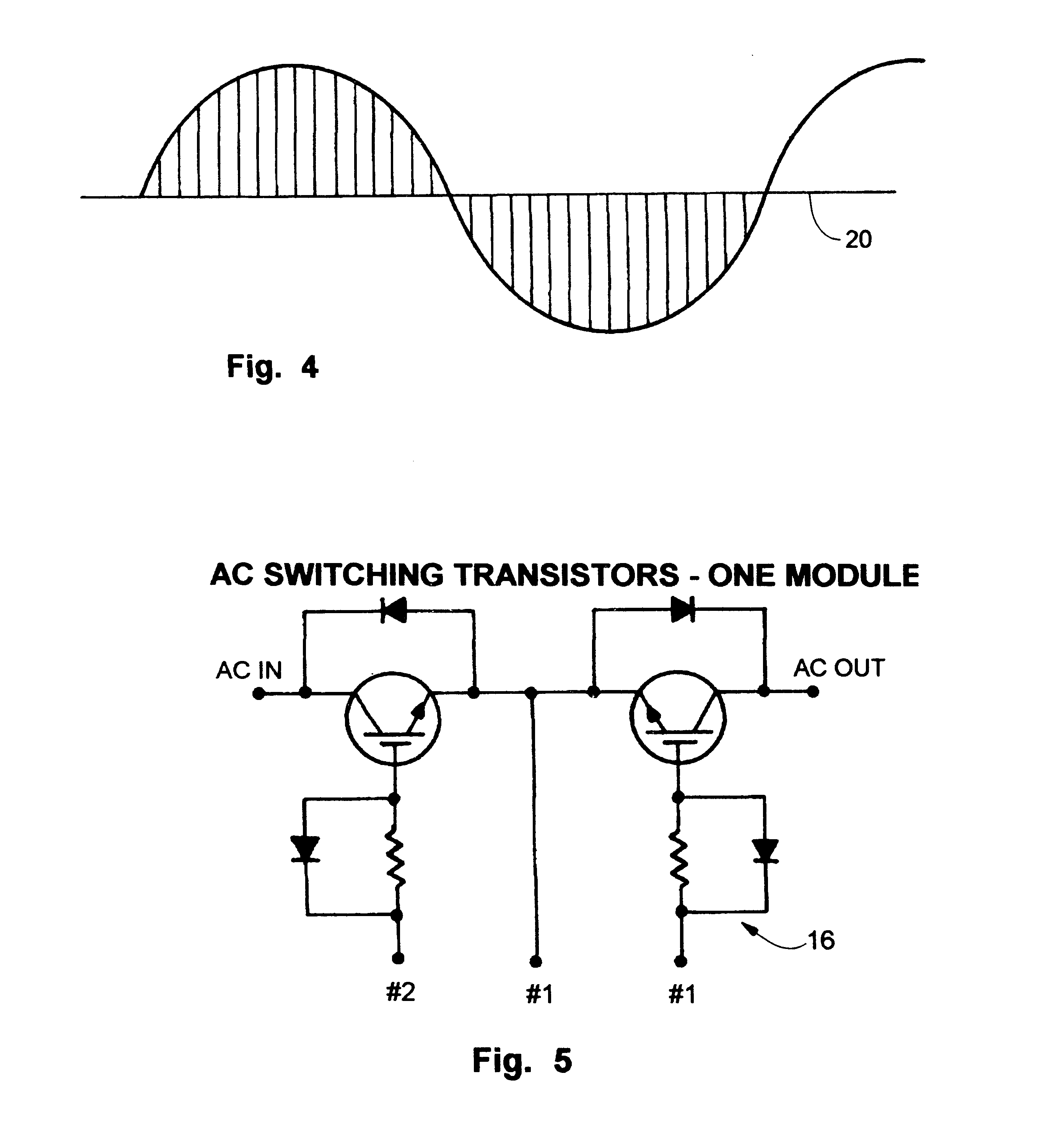
Referring now to the drawing FIGS. 1-9, which depict the current preferred embodiments of the device disclosed herein, specifically FIG. 1 is component depiction of the device 10 in its simplest embodiment featuring a control unit 14 operating a switching means 16 interrupting current flowing in an AC circuit for a plurality of micro second increments. The device is pictured with a switching means 16 interrupting current flow in an AC circuit 12 comprising a live or energized wire 18 and a neutral wire 20 and is depicted interrupting the live or energized wire 18 rather than the neutral wire 20 or ground which provides for the other half of the circuit for electrical energy provided to the load 22 from an AC power supply 24 such as the conventional power grid from a power plant. While insertion into the energized wire 18 on multiple phased circuits with multiple energized wires 18 works best due to the fact that less current needs to be switched, when used in a two-wire single phase...


PUM


Abstract

An electrical power control apparatus and method for a conventional 60 hertz or other conventional frequency electrical AC power supply voltage waveform to proved an effective output current and voltage to an intended load whereby the output frequency is the same as the input frequency. Using a switching means capable of micro switching the current on and off, and a plurality of substantially equal length and duration interruptions of current on both sides of an AC current oscillation, the output effective voltage and resulting current may be preset and controlled to a pre-programmed output level regardless of input voltage having one or more phases. Or, the output voltage and resulting current may be continually monitored with the load integrated into the circuit being monitored and continually adjusted to yield maximum power use savings while avoiding damage to the components attached to the circuit. Additional embodiments provide for use of the micro chopping device as a circuit breaker for over current protection and as a smart circuit breaker to yield a data stream on individual circuit power usage which can be communicated to a monitoring station locally or by electronic transmission of information to a remote monitoring station. Real time monitoring and adjustment of power usage may be accomplished using such communication and two way communication between the device and communicating monitoring station also allow for real time charges for power usage and deduction from prepaid account for real time power usage.

Description

BACKGROUND OF INVENTION1. Field of InventionThe present invention relates AC electrical power which provides energy to homes and businesses. More particularly, it relates to a device and method for creating micro interruptions or micro pulsing of current in an alternating current power supply which provides the current and RMS voltage to an attached inductive or resistive or combination load being energized by the power supply. The device and method herein, by interrupting the current flow in a plurality of micro second interruptions yielding substantially equal total interrupted durations on both sides of an AC duty cycle effectively lowers the actual amount of power consumed by household and business electrical devices, while concurrently being invisible to such devices and allowing them operate within normal parameters and without damage thereto. The disclosed device in some current preferred embodiments also provides the ability to monitor and maintain individual power circuits ...

Claims


Application Information

Patent Timeline
Patent Type & Authority Patents(United States)
IPC IPC(8): H02M5/02H02J13/00H02M5/293H02J3/00
CPCH02J13/0006H02M5/293Y04S20/222Y02B70/3225H02J3/144H02J13/00002Y04S10/30Y02E60/00H02J2310/60H02M1/12
Inventor AMARILLAS, SAL G.ASBURY, JIMMIE
Owner MICROPULSE TECH
Why Eureka
Try Eureka