Rigid reactive cord and methods of use and manufacture

a technology of reactive cords and rigid cords, applied in the direction of fuses, blasting, weapons, etc., can solve the problems of other particulates, inability to push, and inability to easily push the detonating cord through a small passageway

Inactive Publication Date: 2004-02-24
DYNO NOBEL INC
View PDF30 Cites 23 Cited by
  • Summary
  • Abstract
  • Description
  • Claims
  • Application Information

AI Technical Summary

Problems solved by technology

The high degree of flexibility of known detonating cord makes it necessary to either lay the cord where desired or pull it into position since it lacks sufficient rigidity to be pushed into place.
Like-wise, detonating cord cannot easily be pushed through a small passageway, especially if the passageway is irregular or has bends or kinks, and it cannot be pushed so as to penetrate fly ash or another soft substance for any significant distance.
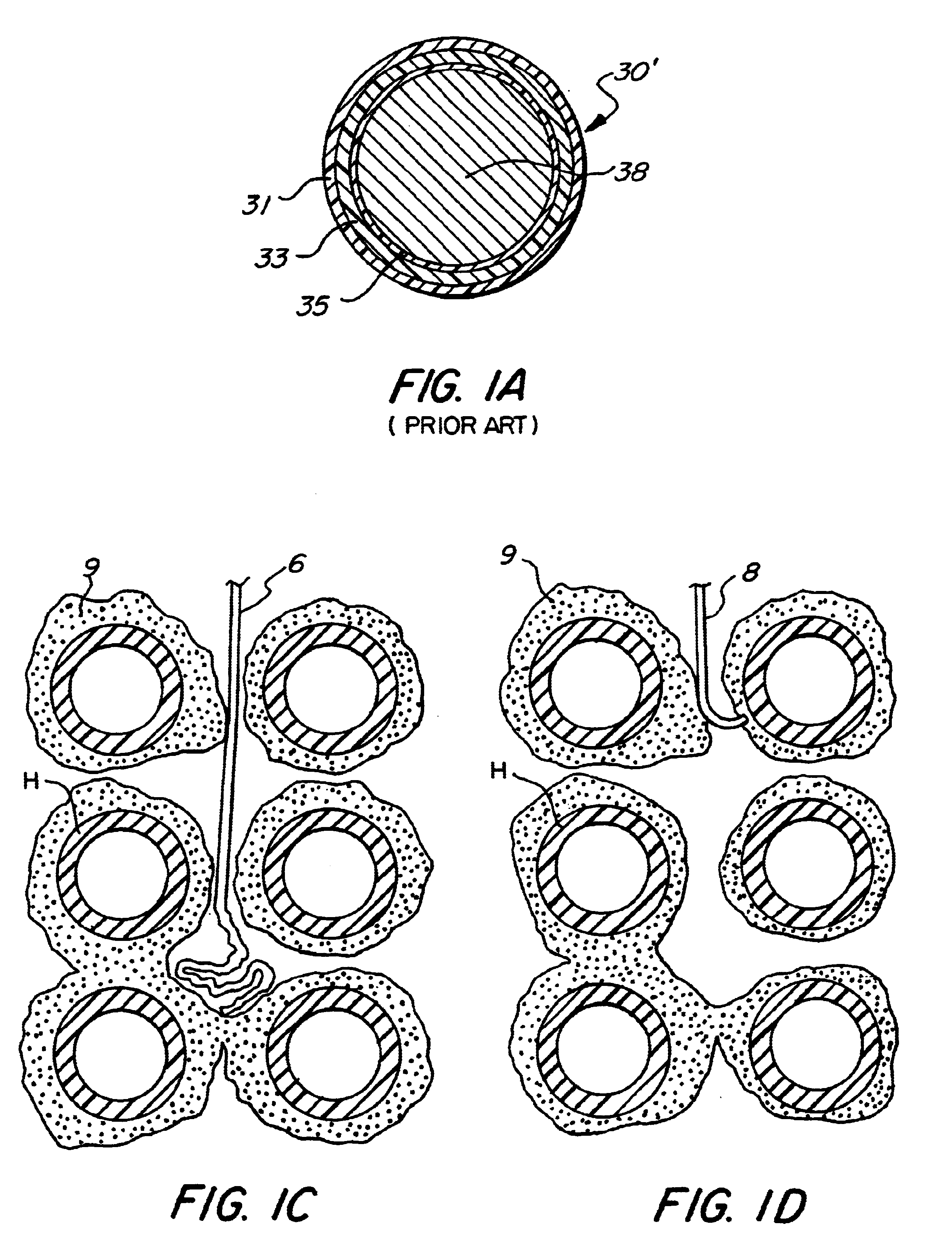
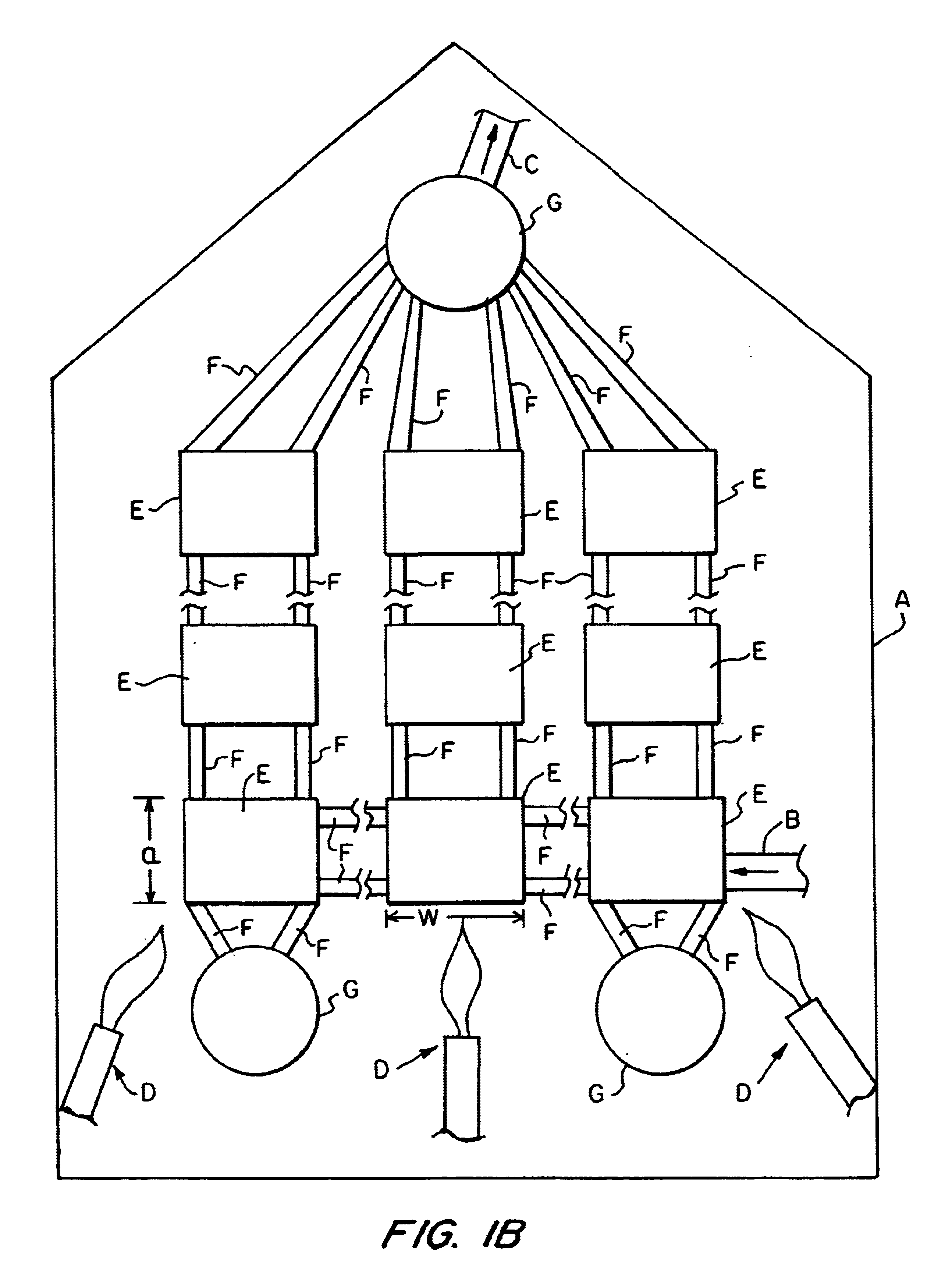
Over time, fly ash, along with other particulates such as dust, builds up and solidifies on the surface of the boiler tubes and may even fill the spaces between the boiler tubes.
When such residues cover the boiler tubes, they thermally insulate the tubes from the flames used to heat them and thereby reduce the efficiency of heat transfer and thus the efficiency of the boiler.
However, if the fly ash fills the spaces between the tubes or if the path between the tubes is narrow or irregular because of the fly ash, passages must be created in the caked fly ash to accommodate the detonating cord, which lacks sufficient rigidity to be pushed through the fly ash or to be guided and forced through a narrow or irregular path from above.
This work is physically demanding and is often done in very confined spaces as the distance between banks of boiler tubes within a typical boiler may be as little as about 4 feet (about 1.2 meters).
It will be appreciated that th...

Method used


Image

  • Rigid reactive cord and methods of use and manufacture
  • Rigid reactive cord and methods of use and manufacture
  • Rigid reactive cord and methods of use and manufacture

Examples


Embodiment Construction

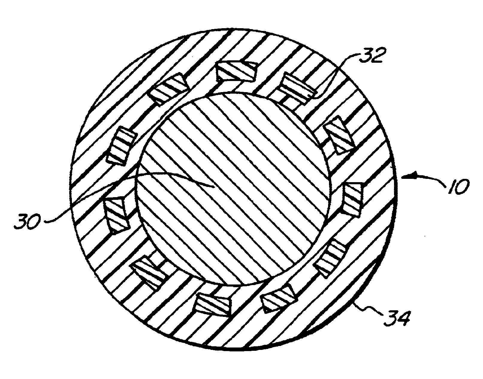
The invention provides a rigid reactive cord having a core of reactive material within a non-metal sheath. The cord of this invention comprises a sheath produced in a process which includes continuous extrusion steps of the type generally known in the art of the manufacture of detonating cord. The resulting product, however, is sufficiently more rigid than prior art non-metal-sheathed reactive cord to permit it to be pushed through a narrow or slightly irregular passage or to be pushed through (i.e., to penetrate or perforate) fly ash as part of a deslagging operation for a boiler or through another material to be fractured. Similarly, it is sufficiently rigid to permit its being pushed upwards, e.g., through a bank of boiler tubes. Therefore, in many circumstances the rigid cord of the present invention obviates the need in deslagging operations for rodding of fly ash and for threading of detonating cord through narrow or irregular passages. The rigidity of this product is demonstr...


PUM


Abstract

The present invention provides a rigid reactive cord such as a detonating cord (10) that includes a core (38) of an energetic material and a rigid non-metal sheath (40) disposed about the core. The cord (10) is sufficiently rigid so that it can be inserted through a material to be fractured or through passages formed therein. A method of using the rigid reactive cord for the removal of combustion residue from boiler tubes is also presented.

Description

1. Field of the InventionThe present invention relates to reactive cords and connectors therefor and, more particularly, to cords which are sufficiently rigid for insertion through a material to be fractured by the cords.2. Related ArtDetonating cords are well known and typically include a core explosive material covered by a non-metal sheath. The sheath may comprise an extruded flexible plastic inner jacket and a flexible, textile outer jacket composed of, for example, polyester yarn. The detonating cord sheath may also include a waterproofing and sealing material such as asphalt disposed about the core. The core explosive may be composed of, for example, pentaerythritol trinitrate (PETN), cyclonite (RDX), homocyclonite (HMX), tetranitrocarbazol (TNC), hexanitrostilbene (HNS), 2-6-bis picryo-amino 3,5-dinitro pyridine (PYX) or black powder, typically with a plasticizer such as a polysulfide and / or one or more other known additives. A typical core loading of PETN may be on the order...

Claims


Application Information

Patent Timeline
IPC IPC(8): C06C5/00C06C5/04F42D3/00
CPCC06C5/04F42D3/00
Inventor WOODALL, MARK E.JOHNSON, DENNIS P.GERST, ERIC C.
Owner DYNO NOBEL INC
Why Eureka
Try Eureka