Rotary-wing aircraft rotor with constant velocity drive

a technology of rotor and constant velocity, which is applied in the direction of propellers, propulsive elements, water-acting propulsive elements, etc., can solve the problems of blade acceleration and deceleration, reducing the overall performance of the helicopter, and disastrous effect on the service life of the rotor components

Inactive Publication Date: 2004-02-24
EUROCOPTER
View PDF12 Cites 39 Cited by
  • Summary
  • Abstract
  • Description
  • Claims
  • Application Information

AI Technical Summary

Benefits of technology

the moments being applied about the axis of rotation of the rotor mast only, which corresponds to the drive torque of the hub, the swivelling capability of this mechanism being therefore only partial, since it offers no freedom of rotation of this mechanism about the mast, the rotor of the invention providing a solution to the disadvantages of state-of-the-art rotors of this type, and such as presented above, by being lighter, simpler, more accessible and therefore more economical to produce and maintain and, more generally, in which the functions of swivelling and driving the hub respectively relative to and by the rotor mast do not necessarily have to be kept separate.
In a manner known in itself, this elastic return assembly may advantageously comprise at least one half of a central laminated spherical thrust bearing, an outer member of which is connected to the hub and an inner member of which is integral in rotation with the mast. This half of a spherical thrust bearing may be fitted under the hub plate, itself attached below the hub casing enclosing the constant velocity drive mechanism and the pivoting means, but, if in addition the elastic return assembly also comprises an upper half of a central laminated spherical thrust bearing, which covers and encloses said hub casing, a central laminated spherical thrust bearing is then obtained which assists in transmitting to the rotor mast the lift and coplanar loads applied to the rotor.

Problems solved by technology

On rotary-wing aircraft rotors, it is known that, since the introduction of the flapping hinge on autogyro and helicopter rotors, tilting the rotor where coning is present, whether this tilting is desired and generated by controlling the cyclic pitch or the unwanted result of the asymmetry between an advancing blade and a retreating blade, causes stresses in the drive plane of the blades which tend to cause the blades to accelerate and decelerate in the course of a revolution of the rotor.
These accelerations and decelerations of the blades over a revolution of rotation have a disastrous effect on the service life of the rotor components, due to the fact that these variations in speed generate stresses which are all the more substantial because the rigidity of the rotor components is high.
These improvements to the original rotary-wing aircraft rotor concepts have led to a rotor fully articulated in pitch, flapping and drag, the main disadvantage of which was to be subject to instability of the ground resonance or air resonance type, which made it necessary to develop and use drag dampers, also known as frequency adapters, or again elastic return drag struts with built-in damping.
In both cases, the presence of the drag dampers increases the aerodynamic drag of the rotor, in particular at the hub and where the hub is connected to the blades, which reduces the overall performance of the helicopter.
However, it is known that rotors which are rigid in drag have the major disadvantage of generating very high stresses when the rotors are tilted.
This speed distortion occurs when the drive and output axes are not co-linear, i.e. in the application considered to driving a rotor in rotation, when cyclic flapping is present.
These two known constant velocity drive systems are not suitable for application to convertible aircraft rotors for the following reasons:
installing Clemens drive links on a convertible aircraft rotor hub very substantially increases the drag of the hub, which reduces its performance and increases operating costs;
tripod joints in particular are not suitable because of the high torque levels encountered on convertible aircraft rotors, which require large diameter and therefore heavy balls to keep the contact surface Hertz pressures at acceptable levels.
Another major disadvantage of this type of hub in addition to the disadvantage regarding the need for accurate tailoring of drive link rigidity is that the enclosing arrangement of the halves of the flapping thrust bearings make it difficult to inspect the links in particular and the torque transmission system in general, as well as impairing accessibility for maintenance purposes.

Method used


Image

  • Rotary-wing aircraft rotor with constant velocity drive
  • Rotary-wing aircraft rotor with constant velocity drive
  • Rotary-wing aircraft rotor with constant velocity drive

Examples


Embodiment Construction

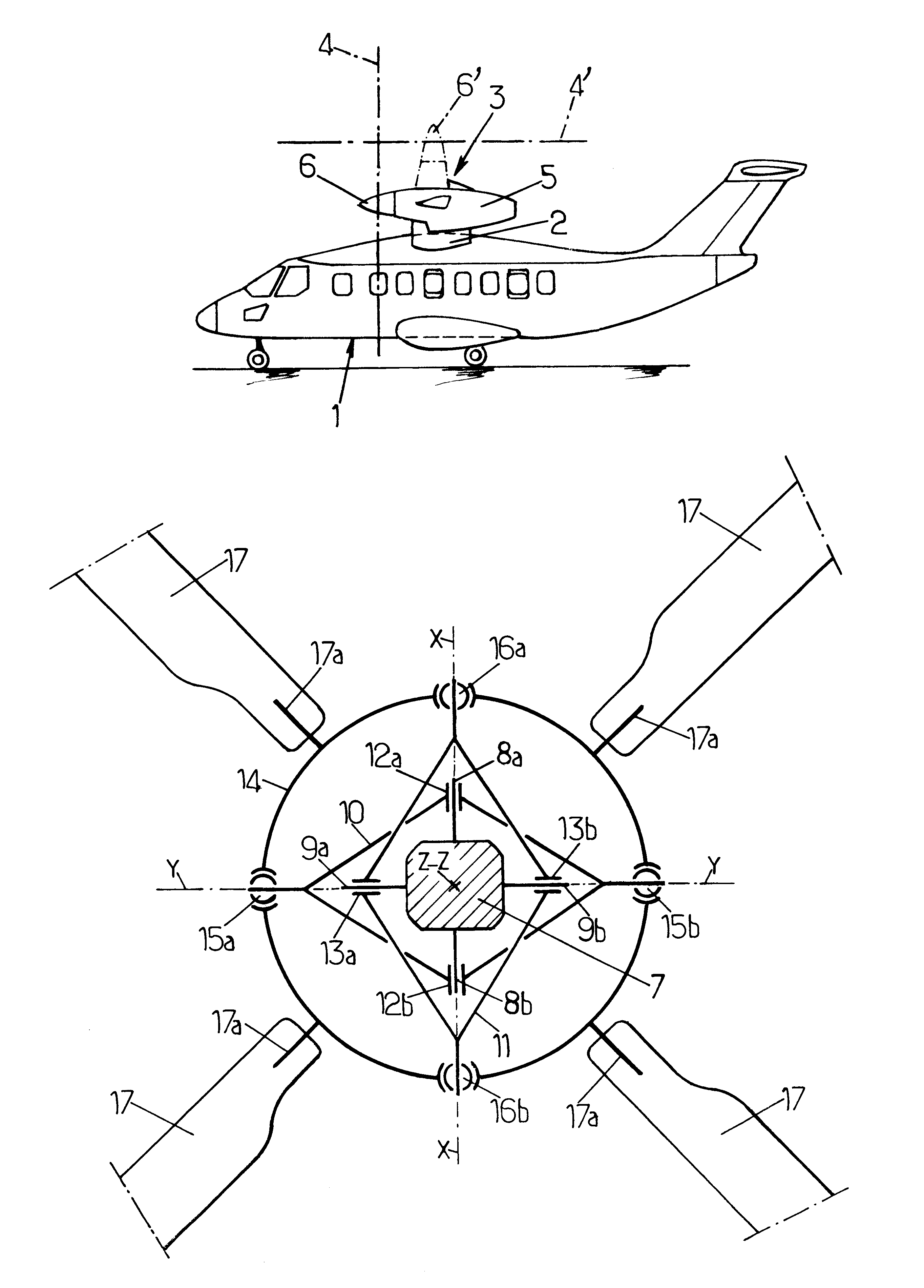
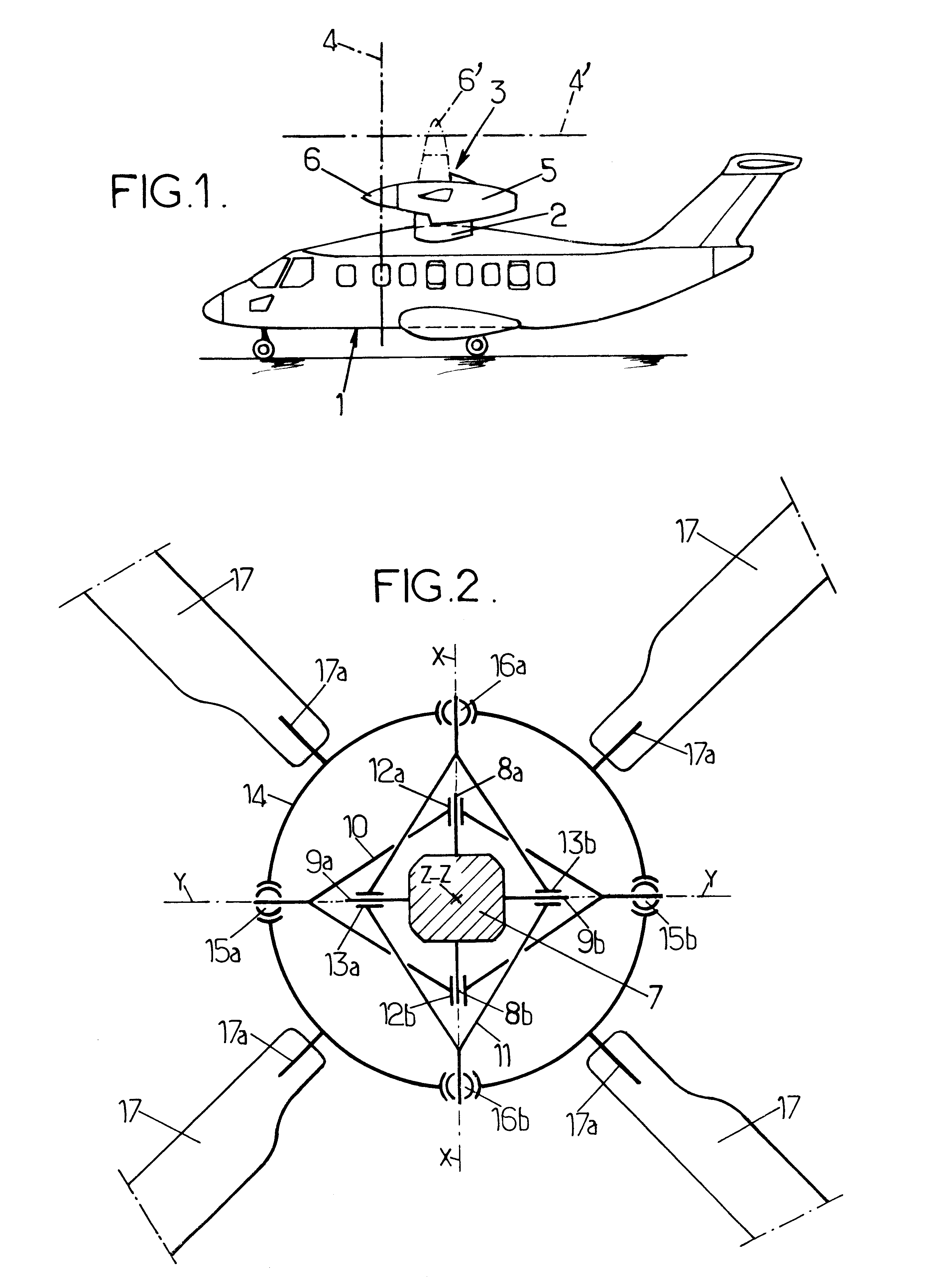
FIG. 2 shows schematically in plan a four-bladed rotor with constant velocity drive according to the invention for equipping the tilting rotors of the convertible aircraft described above with reference to FIG. 1.

In FIG. 2, this four-bladed rotor comprises a rotor mast 7, driven at its base in rotation about its longitudinal axis Z-Z, and the end part of which, at the end opposite the base (not shown) provides cantilever support for two drive end fittings 8a and 8b, diametrically opposite relative to the axis Z-Z and projecting radially towards the outside of the mast 7, perpendicularly to the axis Z-Z, and coaxial about a first diametral axis X-X of the mast 7, so that the end fittings 8a and 8b constitute a first diametral drive arm, integral in rotation with the mast 7. Similarly, the mast 7 supports two other drive end fittings 9a and 9b, also diametrically opposite relative to the axis Z-Z and perpendicular to the latter, cantilevered and projecting radially towards the outside...


PUM


Abstract

A tilting rotor of a convertible aircraft comprises, between the mast and the hub, a constant velocity drive mechanism and pivoting arrangement comprising two gimbals, each of which is driven by the mast and pivots about one respectively of two diametral axes by two diametrically opposite bearings. Each gimbal is also hinged to the hub by ball joint connections diametrically opposite and centred respectively in a radial plane passing through the axis of the mast and through the diametral axis about which the other gimbal pivots. The two resulting trains transmitting torque between the mast and the hub have substantially the same torsional rigidity, and one at least of the components of each torque transmission train exhibits a flexibility in deformation about the axis of rotation of the hub.

Description

The invention relates to a rotary-wing aircraft rotor with constant velocity drive, in particular for a convertible aircraft supporting two generally fixed wings and at least one tilting rotor.Although the constant velocity drive rotor of the invention can be used as a helicopter rotor, in particular as a tail or anti-torque rotor, a particularly advantageous application of such a constant velocity drive rotor consists in fitting it to convertible aircraft with tilting rotors, particularly of the type known and described in FR 2 791 319, FR 2 791 634 and FR 2 798 359, to which reference may advantageously be made for further details. Briefly, such a convertible aircraft with tilting rotors comprises, as shown schematically in FIG. 1, a fuselage 1, of the aircraft fuselage type, supporting two fixed wings 2, for example high wings, raised with respect to the fuselage 1, each wing 2 itself supporting a power pod 3, housing a power unit driving in rotation a rotor 4, represented schema...

Claims


Application Information

Patent Timeline
Patent Type & Authority Patents(United States)
IPC IPC(8): B64C27/32B64C27/00B64C29/00B64C27/52B64C27/35B64C27/41
CPCB64C27/35B64C27/41B64C27/52B64C29/0033
Inventor ZOPPITELLI, ELIORAMPAL, ETIENNE
Owner EUROCOPTER
Why Eureka
Try Eureka