Method for production of white microsilica

a microsilica and white technology, applied in the field of methods, can solve the problems of high cost, health risk, and inability to control the crystalline sio.sub.2, and achieve the effect of high reflectivity and high reflectivity

Inactive Publication Date: 2004-02-24
ELKEM
View PDF3 Cites 15 Cited by
  • Summary
  • Abstract
  • Description
  • Claims
  • Application Information

AI Technical Summary

Benefits of technology

It has surprisingly been found that the method of the present invention can produce microsilica having a very high reflectivity at the same time as maintaining the yield of ferrosilicon or silicon. Such is extremely important for commercial smelting furnaces.
Microsilica having a very high reflectivity can thus, according to the present invention, be produced by changing the ratio between coke and coal in the reduction agent mixture and by keeping the temperature of the gas atmosphere at the top of the furnace above 500.degree. C.
One suitable means for keeping the temperature of the gas atmosphere in the furnace and especially at the top of the furnace above 500.degree. C. in accordance with the present invention is to reduce the amount of air which enters the furnace. By reducing or controlling the in-flow of air to the gas atmosphere in the furnace above the charge, the temperature of the off-gas (gas atmosphere) at the top of the furnace is prevented from cooling to below 500.degree. C. before it leaves the furnace. Controlling the amount of air that enters the furnace is done in a conventional manner using conventional equipment.

Problems solved by technology

The produced microsilica thus has a relatively dark color, which is a problem where microsilica is intended for use in a white product.
Both of these two methods have disadvantages.
Heat treatment of microsilica in a fluidized bed implies an additional step which is very costly and which is difficult to control.
In addition, crystalline SiO.sub.2 constitutes a health risk.
Production of microsilica in a microsilica generator is very costly and it is difficult to design microsilica generators having a high capacity.

Method used


Image

  • Method for production of white microsilica

Examples


example 2

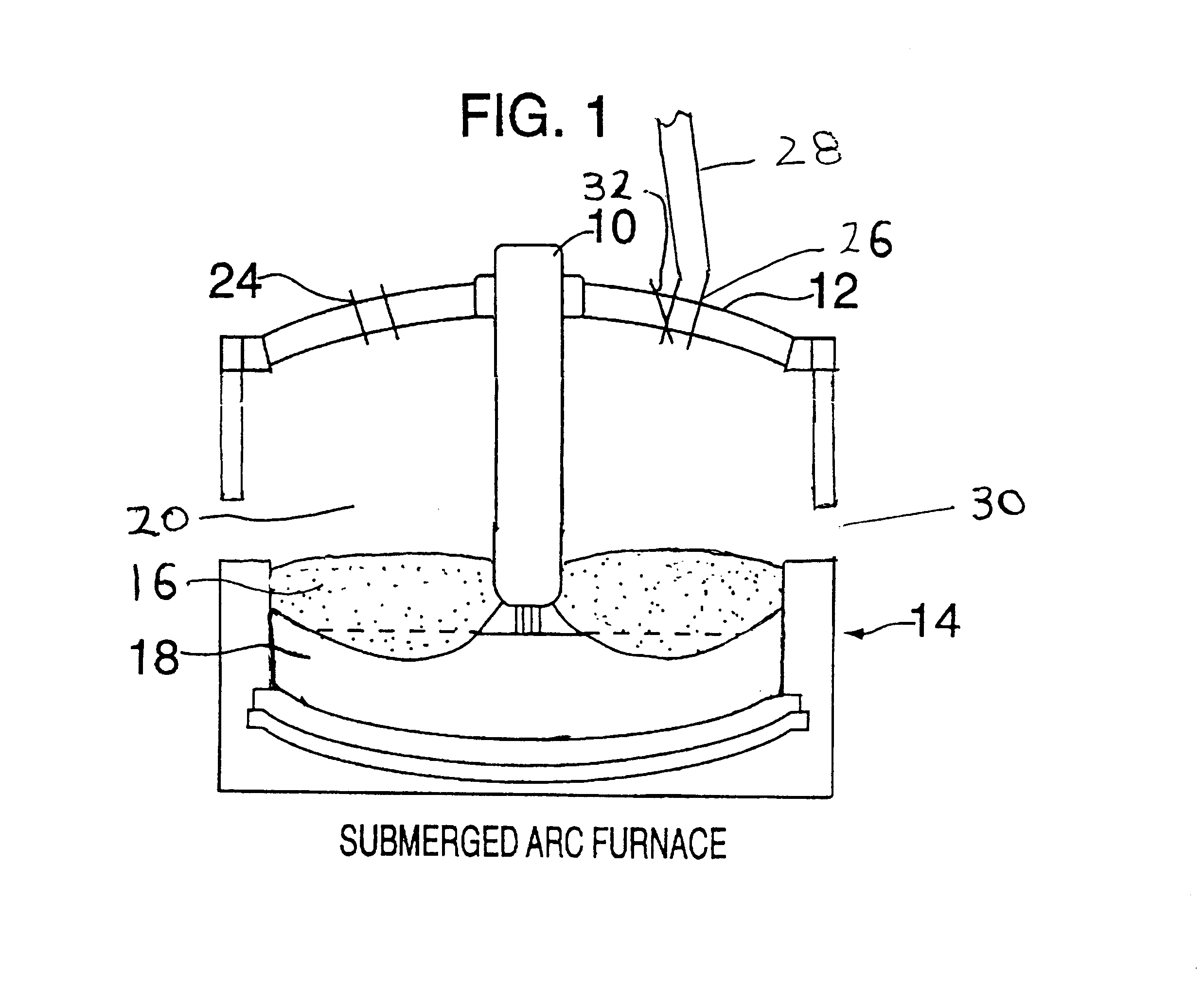
In the same smelting furnace as used in Example 1, 75% FeSi was produced using a charge consisting of quartzite as SiO.sub.2 source and a reduction agent mixture consisting of 80% by weight of coke having a content of volatile matter of 5.2% by weight, and 20% by weight of coal having a content of volatile matter of 33.8% by weight.

The charge was added to the furnace in an amount of 16.32 tons per hour and from the smelting furnace 5.40 tons of 75% FeSi was tapped per hour, while 0.56 tons per hour of microsilica was recovered from the furnace off-gases. The temperature in the furnace gas atmosphere at the top of the furnace was kept constant at 700.degree. C., thus the complete gas atmosphere in the furnace was 700.degree. C. and above.

The power consumption per ton produced ferrosilicon was 7.5 Mwh. The ratio between the amount of volatile matter in the reduction agents and kg produced microsilica was 1.00.

Samples of the produced microsilica were drawn at intervals during the furna...

example 3 (

Comparison)

For comparison purposes the furnace was operated using a conventional reduction agent mixture consisting of 65% by weight of coal and 35% by weight of coke. The ratio between volatile matter in the reduction agent mixture and the amount of produced microsilica was 1.90. The temperature at the top of the furnace was also in this example kept at 700.degree. C. The production of 75% FeSi per hour was the same as in Examples 1 and 2 and the power consumption per ton produced ferrosilicon was 7.7 Mwh.

Samples of the produced microsilica were drawn at intervals and the reflectivity was measured. The results showed that the produced microsilica had a reflectivity of 40.

A comparison of the results in Examples 1 and 2 and the results in Example 3 shows that by the method of the present invention a substantial increase in whiteness of the produced microsilica is obtained at the same time as the power consumption and the yield of FeSi is not affected. This is very surprising as the p...


PUM

PropertyMeasurementUnit
reflectivityaaaaaaaaaa
temperatureaaaaaaaaaa

Abstract

The present invention relates to a method for producing microsilica having a reflectivity between 65 and 90% in a smelting furnace for production of ferrosilicon or silicon by using a charge comprising an SiO2 source and a solid carbonaceous reduction agent, where microsilica is recovered from the off-gases from the smelting furnace, wherein the solid reduction agent supplied to the furnace contains an amount of volatile matters of less than 1.25 kg per kg produced microsilica and that the temperature in the gas atmosphere in the furnace above the charge is kept above 500° C.

Description

The present invention relates to a method for production of microsilica having a high light reflectivity or whiteness.Microsilica is normally produced as a by-product during production of ferrosilicon and silicon in electric reduction furnaces where a charge comprising a SiO.sub.2 source and one or more solid carbonaceous reduction agents is reacted to form ferrosilicon or silicon. In this process, gaseous SiO is formed as an intermediate product in the reaction zone in the furnace and the gas moves upwards through the charge. A part of the SiO gas is condensed in the cooler charge above the reaction zone, while the remaining part of the SiO gas escapes from the charge, is quickly cooled and oxidized by air which is supplied to the furnace, above the charge, and forms particulate amorphous SiO.sub.2. The particulate SiO.sub.2 is carried upward out of the furnace in the off-gas and is recovered from the furnace off-gas in filters, normally baghouse filters. Microsilica produced in th...

Claims


Application Information

Patent Timeline
Patent Type & Authority Patents(United States)
IPC IPC(8): C01B33/00C01B33/025C01B33/18
CPCB82Y30/00C01B33/025C01B33/181C01P2004/62C01P2004/64C01P2006/10C01P2006/11C01P2006/12C01P2006/60C01P2006/80C01P2006/82
Inventor DASTOL, MAGNETVEIT, HALVARDDINGSOYR, ELDARRONNING, PERHARSAKER, SVEIN
Owner ELKEM
Why Eureka
Try Eureka