Piezoelectric actuator

a technology of actuators and actuators, applied in the direction of valve operating devices/release devices, fuel injection pumps, machines/engines, etc., can solve the problem of affecting the heat dissipation of the valve housing

Inactive Publication Date: 2004-03-02
ROBERT BOSCH GMBH
View PDF9 Cites 29 Cited by
  • Summary
  • Abstract
  • Description
  • Claims
  • Application Information

AI Technical Summary

Benefits of technology

In view of the above mentioned, the object of the invention is to produce a piezoelectric actuator of this generic type, which is protected against contamination and moisture even before installation in the valve housing, in which a simple centering of the actuator in the valve housing is achieved. Simultaneously, an electric insulation of the actuator to the valve housing and favorable heat transmission from the actuator to the valve housing are achieved.
According to an essential aspect of the invention, the actuator--at least including the top plate--is enclosed by an electrically insulating elastomer sleeve so that the actuator with the elastomer sleeve rests snugly against the inner wall of the axial bore of the valve housing in the vicinity of the actuator. Before insertion of the actuator into the axial bore, this elastomer sleeve preferably has a convex shape whose diameter exceeds the inner diameter of the axial bore of the housing over the entire axial length of the actuator body. As a result, the actuator is centered according to the invention over the entire length of the actuator body after insertion into the valve housing, is electrically insulated from the valve housing, and is protected against contamination and damage before installation. At the same time favorable heat transmission from the actuator body to the valve housing is assured. In the piezoelectric actuator according to the invention, at least the bottom plate is integrated with the actuator body by means of the elastomer sleeve and consequently, the elastomer sleeve adhering to the actuator body and to at least the bottom plate leads to a better centering during installation. The integration of the top and bottom plate also prevents a rotation of the actuator so long as at least the bottom plate is secured in the valve housing.
If the top and bottom plate are completely or partially made of electrically insulating material, then the short-circuit danger on the top and bottom of the actuator can be considerably reduced. Even with a metallic top and bottom plate, the encapsulation within the elastomer sleeve greatly improves the short-circuit safety.
Intentional air inclusions in the elastomer can, if necessary, be used to reduce compressive strains produced by thermal expansion.
If necessary, the centering of the actuator body can be improved by means of inserted centering rings made of a stronger polymer.
Optionally, the elastomer sleeve is filled with thermally conductive supplementary particles which increase the thermal conductivity of the elastomer sleeve and thereby improve the dissipation of the heat produced during operation of the actuator body.

Problems solved by technology

This produces the disadvantage that the heat dissipation to the valve housing is impeded by the air gap.

Method used


Image

  • Piezoelectric actuator
  • Piezoelectric actuator
  • Piezoelectric actuator

Examples


Embodiment Construction

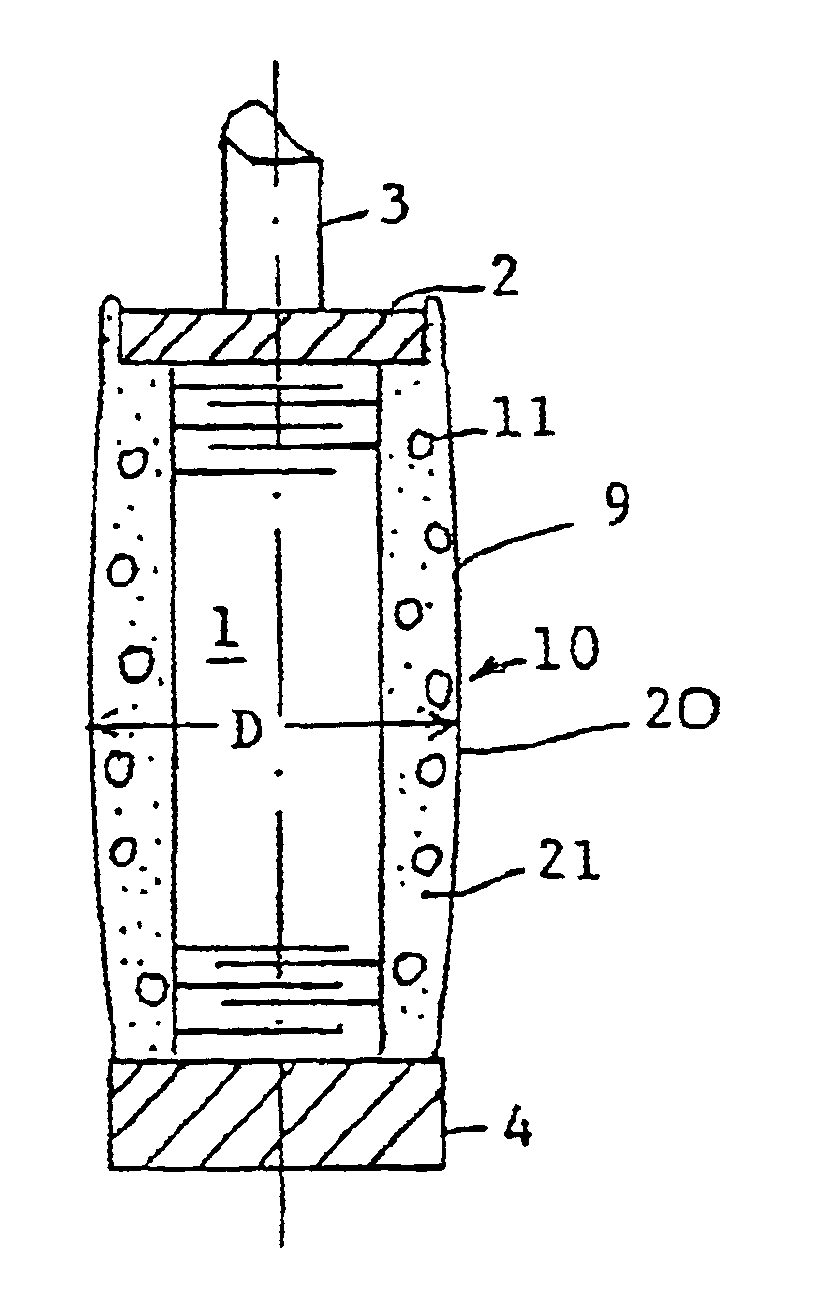
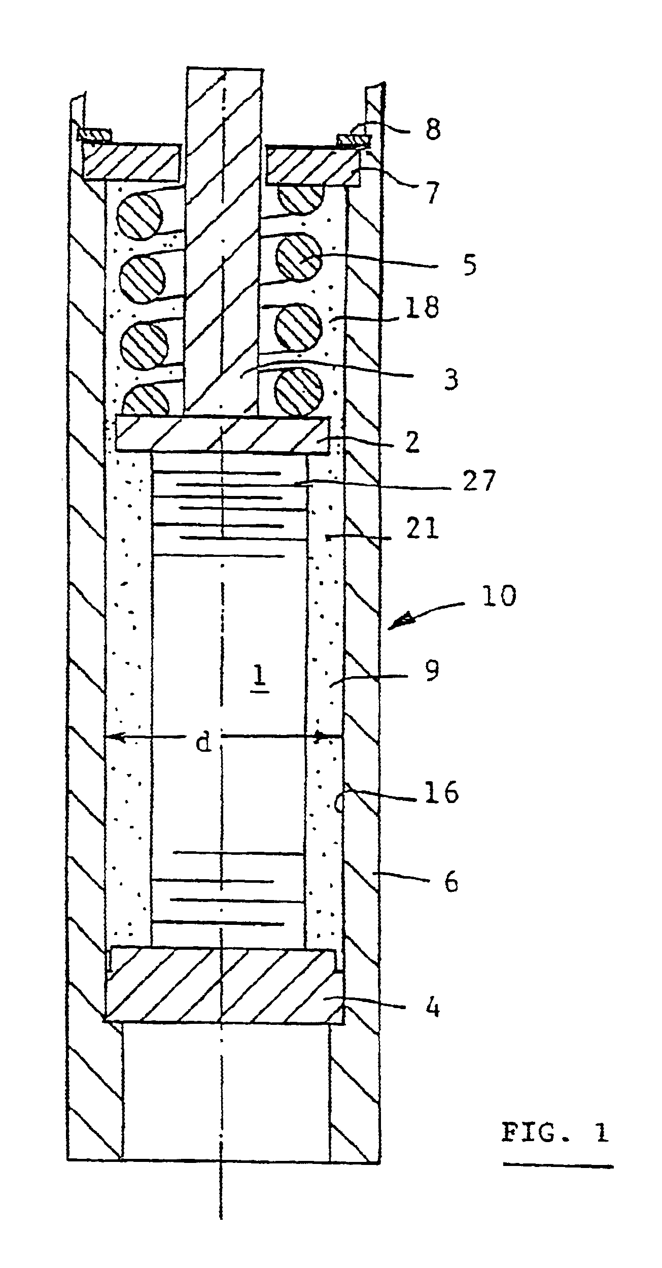
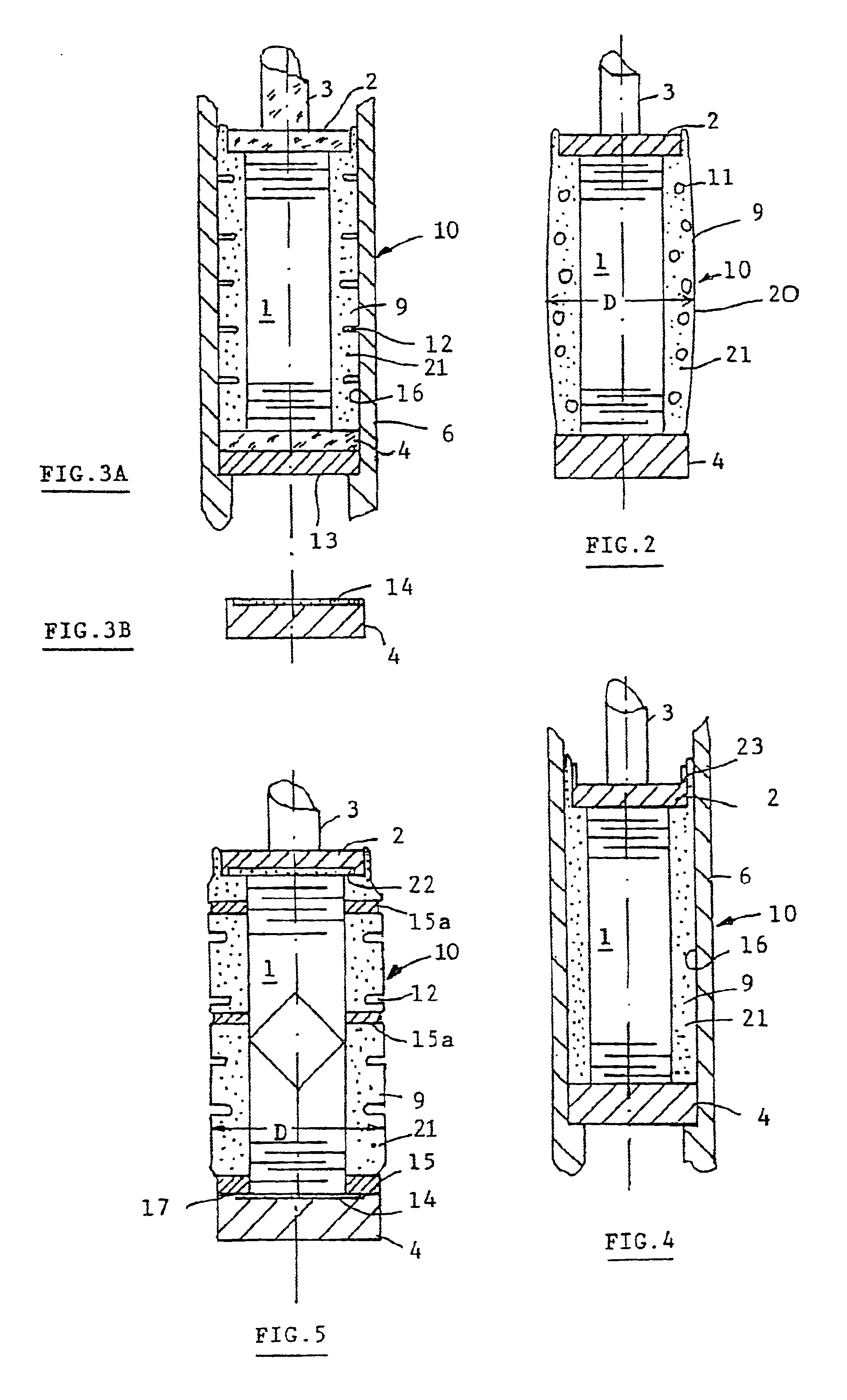
FIG. 1 is a schematic longitudinal section through a piezoelectric actuator which is labeled as a whole with the reference numeral 10 and which has a multilayered piezoelectric actuator body 1 in the form of a multilayered laminate (not shown) made up of stacked layers of piezoelectric material with intervening metallic or electrically conductive layers that function as electrodes 27. The end faces of the actuator body 1 are respectively contacted by a top plate 2 oriented toward the valve having an axially protruding valve tappet 3 and a bottom plate 4 at the opposite end affixed to a valve housing 6, and the actuator 10 is installed in an axial bore 16 of the steel valve housing 6. At its ends, the actuator 10 is prestressed, for example, by means of a helical spring 5, since the actuator 10 can only transmit compressive forces and must not be subjected to any tensile stress during dynamic operation. The frictional engagement of the initial stress is produced by means of the metal...


PUM


Abstract

The invention relates to a piezoelectric actuator, in particular for actuating control valves or injection valves in motor vehicles, having an actuator body in the form of a multilayered laminate made up of stacked layers of piezoelectric material with intervening metallic or electrically conductive layers that function as electrodes, and the end faces of this actuator body are respectively contacted by a top plate oriented toward the valve having an axially protruding valve tappet and a bottom plate at the opposite end, wherein the actuator rests in an axial bore of a valve housing and is prestressed at the ends in the axial direction between the top plate and the bottom plate by means of a spring element. According to the invention, the actuator-at least including the top plate-is enclosed by an electrically insulating elastomer sleeve so that when installed, the actuator with the elastomer sleeve rests snugly against the inner wall of the axial bore of the valve housing in the vicinity of the actuator.

Description

PRIOR ARTThe invention relates to a piezoelectric actuator, in particular for actuating control valves or injection valves in motor vehicles, having an actuator body in the form of a multilayered laminate made up of stacked layers of piezoelectric material with intervening metallic or electrically conductive layers that function as electrodes, and the end faces of this actuator body are respectively contacted by a top plate oriented toward the valve having an axially protruding valve tappet and a bottom plate at the opposite end, wherein the actuator rests in an axial bore of a valve housing and is prestressed at the ends in the axial direction between the top plate and the bottom plate by means of a spring element.A piezoelectric actuator of this kind has been disclosed, for example, by DE 196 50 900 A1 from Robert Bosch GmbH.If a pulsating electrical voltage is applied to their electrode layers, multilayered piezoelectric actuators of this kind execute analogously pulsating stroke...

Claims


Application Information

Patent Timeline
Patent Type & Authority Patents(United States)
IPC IPC(8): F02M59/00F02M59/46F02M47/02F02M51/06H01L41/00H01L41/083H01L41/053F02M63/00F02M51/00F03G7/00F16K31/00F16K31/02H02N2/00H02N2/04
CPCF02M47/027F02M51/0603F02M63/0026H01L41/083H01L41/0533H01L41/0536H10N30/883H10N30/886H10N30/50F16K31/00
Inventor HEINZ, RUDOLF
Owner ROBERT BOSCH GMBH
Why Eureka
Try Eureka