High frequency power amplifier

a power amplifier and high frequency technology, applied in the direction of amplifier combinations, gain control, transmission, etc., can solve the problems of direct impact on the efficiency of the amplifier as a whole, and the inability to control the output of the amplifier by changing the inputs of the amplifier like a linear amplifier

Inactive Publication Date: 2004-03-02
SONY CORP
View PDF3 Cites 93 Cited by
  • Summary
  • Abstract
  • Description
  • Claims
  • Application Information

AI Technical Summary

Benefits of technology

According to the first preferred embodiment of the invention, the high frequency power amplifier is provided with the means or unit for controlling the output of the amplifier. The means controls the means for turning on or off the operation of the portion of the plurality of transistors, which are connected in parallel and are switch-driven, turning on the operation of the portion of the plurality of transistors in the high output power region and turning off the operation of the portion of the plurality of transistors in the low output power region. Consequently, the reduction of efficiency on the side of the other portion of the plurality of transistors, having variable drain voltage according to the control value, can be suppressed to a minimum. Thus, it becomes possible to control the output power of the amplifier while keeping relatively high efficiency.
According to the second and the third preferred embodiments of the invention, as the amplifier being provided with the means for optimizing setting of the circuit constant of the matching circuit according to the output of the amplifier, it becomes possible to achieve the improvement of the stability thereof as well as the improvement of the efficiency thereof, in addition to the advantages of the first embodiment. Furthermore, the amplifier according to the third preferred embodiment switches the circuit constant in accordance with the turning on or off of the operation of the portion of the plurality of transistors, and thereby the operation of the amplifier can easily be implemented by means of a common controller.
According to the fourth and the fifth preferred embodiments of the invention, as the amplifier is provided with the means or unit (such as the DC-DC converter) for enabling the continuous control of the drain voltage to be applied to the transistors, it becomes possible to adjust the output power of the amplifier most suitably for preventing waste of electric power and for performing a more suitable operation thereof in addition to the advantages of the aforesaid first to the third preferred embodiments.

Problems solved by technology

However, because the saturated type amplifier operates FET's in their saturated states, it is impossible to control the outputs of the amplifier by changing the inputs thereof like a linear amplifier.
As a result, when adopting the drain voltage control method, the efficiency of the amplifier as a whole is directly affected by the efficiency of the DC-DC converter.

Method used


Image

  • High frequency power amplifier
  • High frequency power amplifier
  • High frequency power amplifier

Examples


Embodiment Construction

A high frequency power amplifier according to a preferred embodiment of the present invention is described in the following in association with the attached drawings.

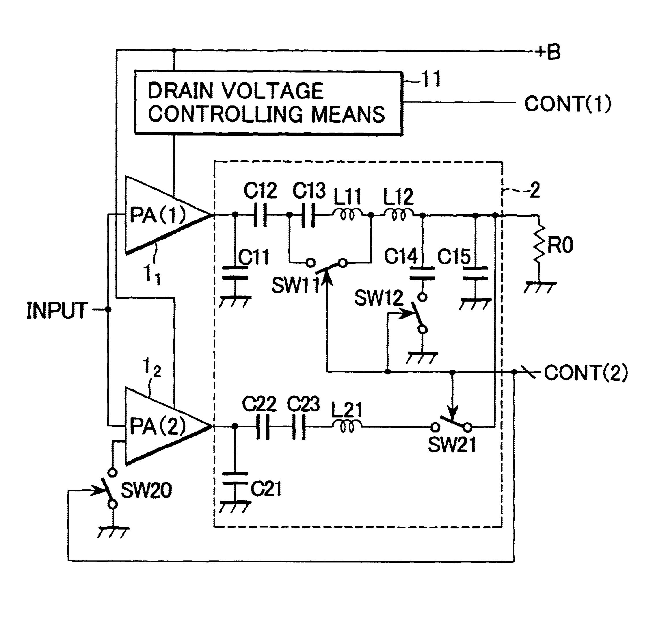
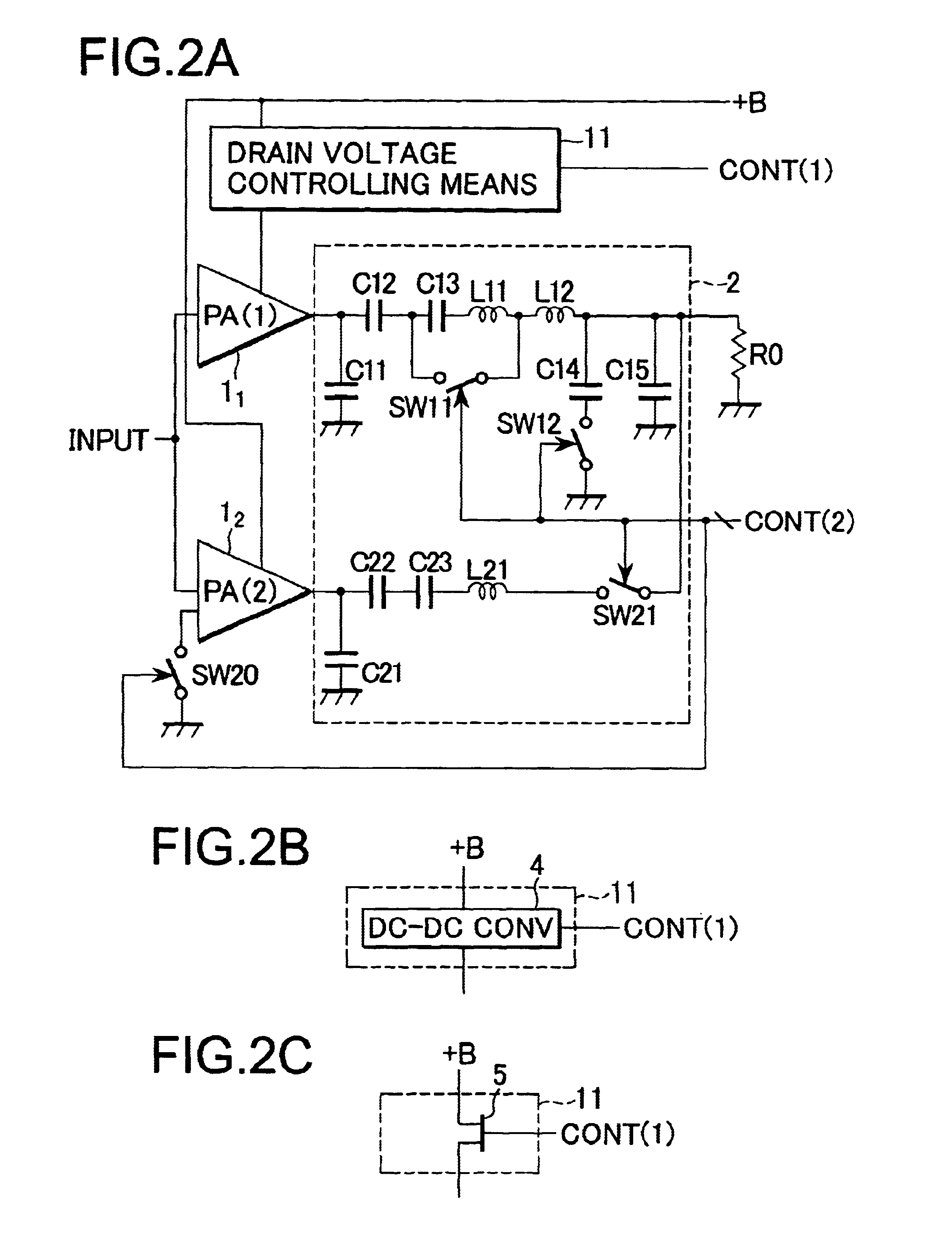
The present invention concerns the high frequency power amplifier the output power of which can continuously be controlled by the changes of the drain voltages of switching-driven transistors. The present invention has been conceived taken in account improving efficiency of the amplifier more than a conventional amplifier employing a similar system.

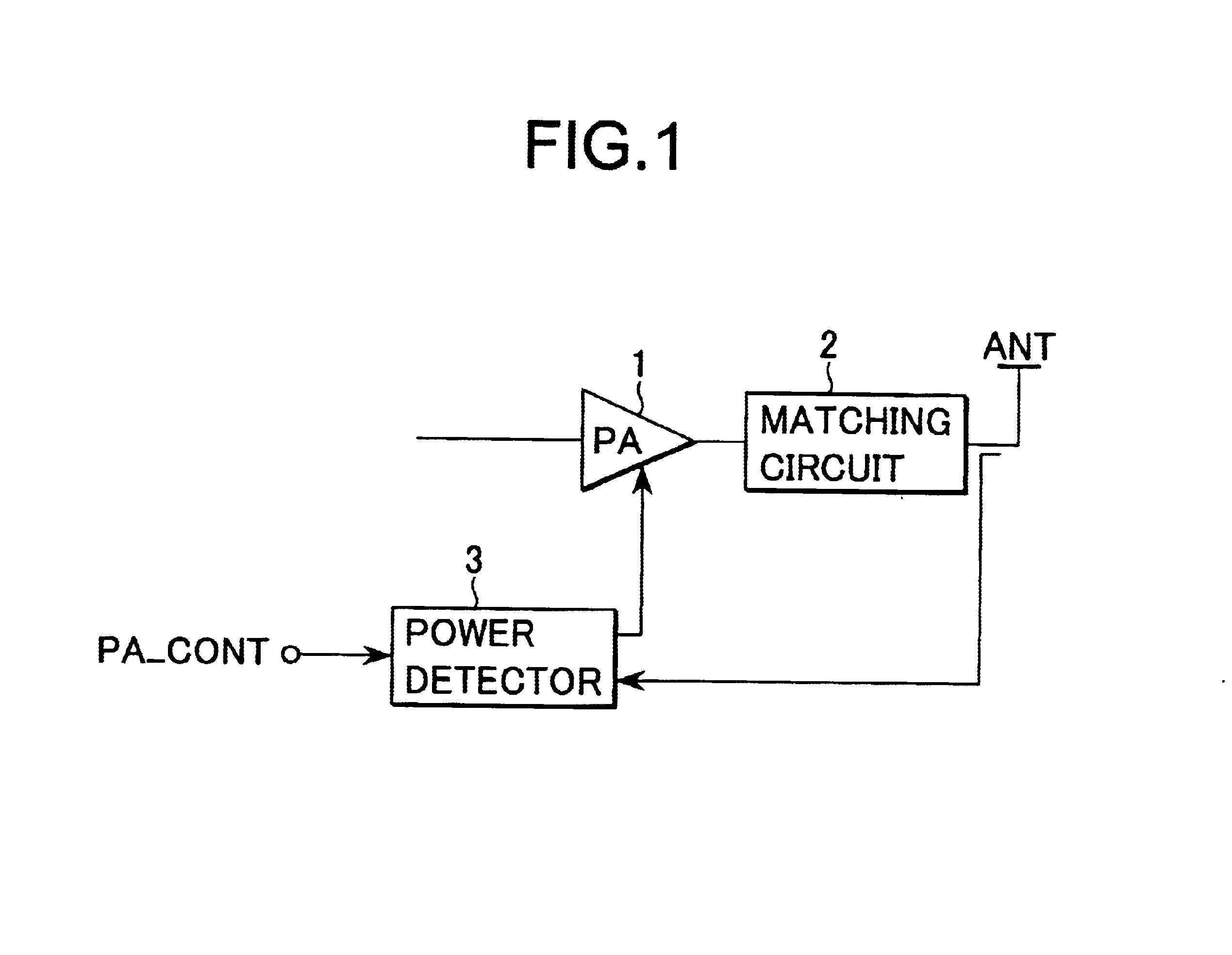
Various cases can be considered in which continuous control of the output of a high frequency power amplifier is needed. In the following, the case where the continuous control is applied to a high frequency power amplifier in an antenna output stage of a communication device for digital mobile communication (such as a cellular phone or the like) is shown as a suitable example. Here, a case is exemplified and the detail thereof is described in the following. In the case, the ...


PUM


Abstract

A high-frequency power amplifier system including a plurality of individual amplifiers connected in parallel, the amplifiers including switching-driven FET's. A fixed drain voltage is applied to one amplifier and a variable drain voltage is applied to another amplifier through a section including a DC-DC converter that converts the voltage according to a control value of a control signal. The turning on and off of the operation of the power amplifier is controlled by a control signal. Also, the circuit constants of a matching circuit are variable. In a high output power region, the power amplifier is turned on and, in a low output power region, turned off. Thereby, the decrease of efficiency of the power amplifier, owing to the DC-DC converter, may be suppressed to a minimum. The matching of the amplifier is adjusted when the power amplifier is switched on or off so as to improve efficiency. Consequently, it becomes possible to continuously control the output of the amplifier.

Description

This application claims priority to Japanese Patent Application No. JP 2001-161918, filed on May 30, 2001, the disclosure of such application being herein incorporated by reference to the extent permitted by law.1. Field of the InventionThe present invention relates to a high frequency power amplifier using switching-driven transistors, and more particularly, to a high frequency power amplifier permitting continuously controlled power output and attaining improved amplification efficiency.2. Description of the Related ArtHigh frequency power amplifiers are conventionally used as amplifiers for antenna output stages of communication devices, or the like. There are amplifiers having various characteristics and, among them, amplifiers having high efficiency as amplifiers are especially suitable for use in the transmitting sections of communication device terminals for digital mobile communication utilizing digital cellular phones or the like. Merits on low electric power consumption, n...

Claims


Application Information

Patent Timeline
Patent Type & Authority Patents(United States)
IPC IPC(8): H03G1/00H03F1/02H03F3/217H03F3/68
CPCH03F1/0238H03F1/56H03F3/211H03G1/0088H04B1/0458H04B1/0483H03F2200/387H03F2200/391H03F2200/421H03F2203/21157H03F2203/21175
Inventor HAREYAMA, NOBUO
Owner SONY CORP
Why Eureka
Try Eureka