
Method and apparatus for coding bits of data in parallel

a technology of data coding and data, applied in the field of data communication, can solve the problems of long processing delay using the conventional technique, adversely affecting the performance of the communication system, and affecting performance,

Inactive Publication Date: 2004-03-02
QUALCOMM INC
View PDF5 Cites 11 Cited by
  • Summary
  • Abstract
  • Description
  • Claims
  • Application Information

AI Technical Summary

Benefits of technology

The present invention relates to data communication systems and methods for coding data using multiple encoders in parallel to reduce delays and improve coding efficiency. By coding multiple bits in parallel, the overall processing delays for the system can be significantly reduced, which can impact the performance of the communication system. The use of a concatenated encoder with two or more encoders can be serially concatenated to form a Turbo encoder commonly used in CDMA communications systems. The memory used in the system can be designed to store and retrieve data in parallel, and the system can include a set of N multiplexers to provide N code bits in parallel to the second encoder. The technical effects of the invention include improved coding efficiency, reduced processing delays, and improved performance of the communication system.

Problems solved by technology

However, for improved coding efficiency, it is desirable to process and code larger sized packets, which can result in longer processing delays using the conventional technique that serially codes data.
The long processing delays may adversely impact the performance of the communications system.
If the processing delays are excessively long, the link conditions may have changed by the time of the data transmission, and performance may be compromised or adversely affected.

Method used


Image

  • Method and apparatus for coding bits of data in parallel
  • Method and apparatus for coding bits of data in parallel
  • Method and apparatus for coding bits of data in parallel

Examples


Embodiment Construction

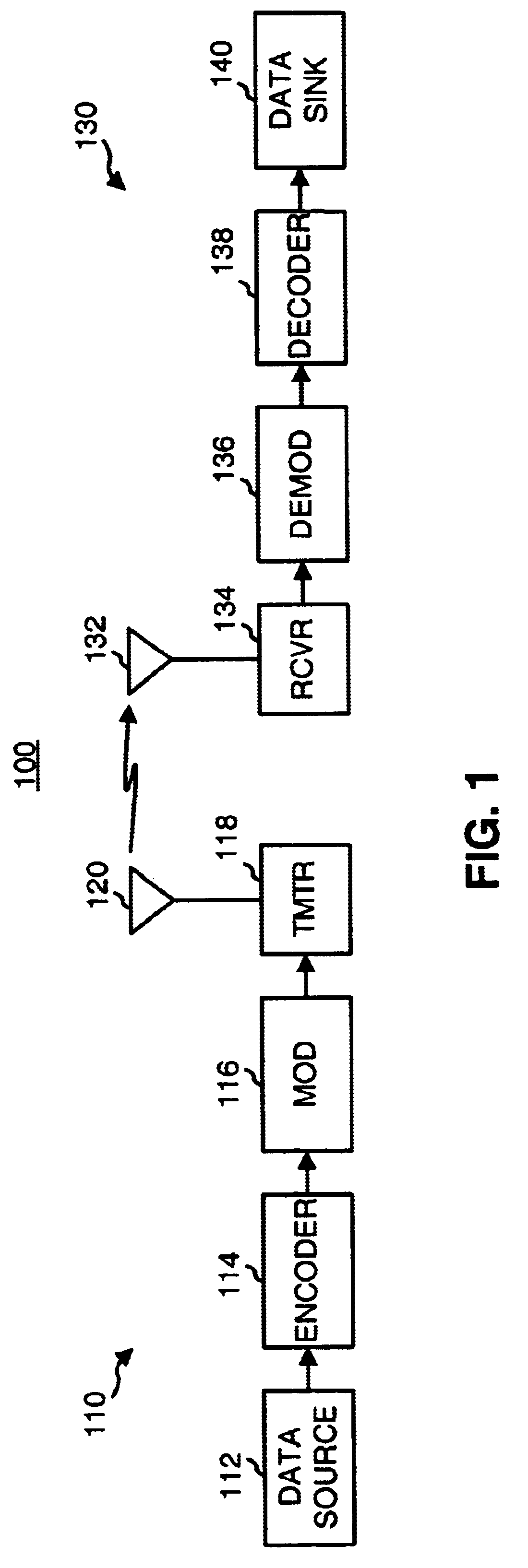
FIG. 1 is a simplified block diagram of an embodiment of a communications system 100 in which various aspects of the present invention may be implemented. At a transmitter unit 110, traffic data is sent, typically in packets or frames, from a data source 112 to an encoder 114 that formats and codes the data using a particular coding scheme. Encoder 114 typically further performs interleaving (i.e., reordering) of the code bits. A modulator (MOD) 116 then receives, channelizes (i.e., covers), and spreads the coded data to generate symbols that are then converted to one or more analog signals. The analog signals are filtered, (quadrature) modulated, amplified, and upconverted by a transmitter (TMTR) 118 to generate a modulated signal, which is then transmitted via an antenna 120 to one or more receiver units.

At a receiver unit 130, the transmitted signal is received by an antenna 132 and provided to a receiver (RCVR) 134. Within receiver 134, the received signal is amplified, filtered...


PUM


Abstract

A concatenated encoder capable of coding multiple data bits in parallel and including a first (outer) encoder, a memory, and a second (inner) encoder coupled in cascade. The first encoder receives and codes M data bits in parallel in accordance with a first coding scheme to generate MR code bits. The memory receives and stores unpunctured ones of the MR code bits from the first encoder. The second encoder receives and codes N code bits in parallel in accordance with a second coding scheme to generate coded data. M and N can be any values (e.g., M>=8, N>=4). Each encoder can be a (e.g., a rate ½) convolutional encoder that implements a particular polynomial generator, and can be implemented with one or more look-up tables, a state machine, or some other design.

Description

I. Field of the InventionThe present invention relates to data communications. More particularly, the present invention relates to coding multiple bits of data in parallel (e.g., using a multiple-port memory) to significantly reduce delays associated with coding.II. Description of the Related ArtIn a typical digital communications system, data is processed, modulated, and conditioned at a transmitter unit to generate a modulated signal that is then transmitted to one or more receiver units. The data processing may include, for example, formatting the data into a particular frame format, coding the formatted data with a particular coding scheme to provide error detection and / or correction at the receiver units, channelizing (i.e., covering) the coded data, and spreading the channelized data over the system bandwidth. The data processing is typically defined by the system or standard being implemented.At the receiver unit, the transmitted signal is received, conditioned, demodulated, ...

Claims


Application Information

Patent Timeline
Patent Type & Authority Patents(United States)
IPC IPC(8): H03M13/23H03M13/29H03M13/00H04L1/00
CPCH03M13/23H03M13/29H03M13/2903H03M13/2972H03M13/6561H04L27/26
Inventor SALVI, ROHAN S.HOWARD, MICHAEL A.
Owner QUALCOMM INC
Learn More