Charged beam exposure apparatus having blanking aperture and basic figure aperture

a charge beam and blanking aperture technology, applied in the field of electron or ion charged beams, can solve the problems of insufficient throughput, longer exposure time, and inability to obtain throughpu

Inactive Publication Date: 2004-03-09
KK TOSHIBA
View PDF9 Cites 21 Cited by
  • Summary
  • Abstract
  • Description
  • Claims
  • Application Information

AI Technical Summary

Problems solved by technology

In the VSB exposure, since exposure is repeated by dividing a pattern into a lot of minute rectangular shots, the exposure takes longer time, and there is a disadvantage that throughput cannot be obtained.
For this reason, the variable shaped beam exposure is also used, and sufficient throughput cannot be obtained.
Further, in this CP exposure, there arises a problem that thermal expansion warpage of a mask, which occurs when an electron beam is emitted to the mask, is large and pattern position accuracy is lowered.
This electron-beam mask transfer system has a problem that mask production costs an enormous amount of money.
However, this BAA system has a problem that an apparatus for controlling signal of the BAA section is very expensive.

Method used


Image

  • Charged beam exposure apparatus having blanking aperture and basic figure aperture
  • Charged beam exposure apparatus having blanking aperture and basic figure aperture
  • Charged beam exposure apparatus having blanking aperture and basic figure aperture

Examples


second embodiment

(Second Embodiment)

Next, there will be explained below the creating method according to the second embodiment which is obtained by developing the exposure data creating method explained in the first embodiment. Moreover, there will be explained below the exposure method according to the second embodiment using the developed creating method. FIG. 11 is a flow chart showing the exposure data creating method according to the second embodiment.

In the exposure data creating method according to the second embodiment, at step S4 data of the layout in the semiconductor apparatus are divided into a vertical line pattern and a horizontal line pattern which take reduction in the exposure into consideration.

Next, at step S5 widths of the vertical line patterns are enlarged so that a first pattern, in which the adjacent vertical line patterns are integrated, is created. Further, widths of the horizontal line patterns are enlarged so that a second pattern, in which the adjacent horizontal line pa...

third embodiment

(Third Embodiment)

The third embodiment will explain the case where LSI type patterns are used as the basic figures of the basic figure apertures.

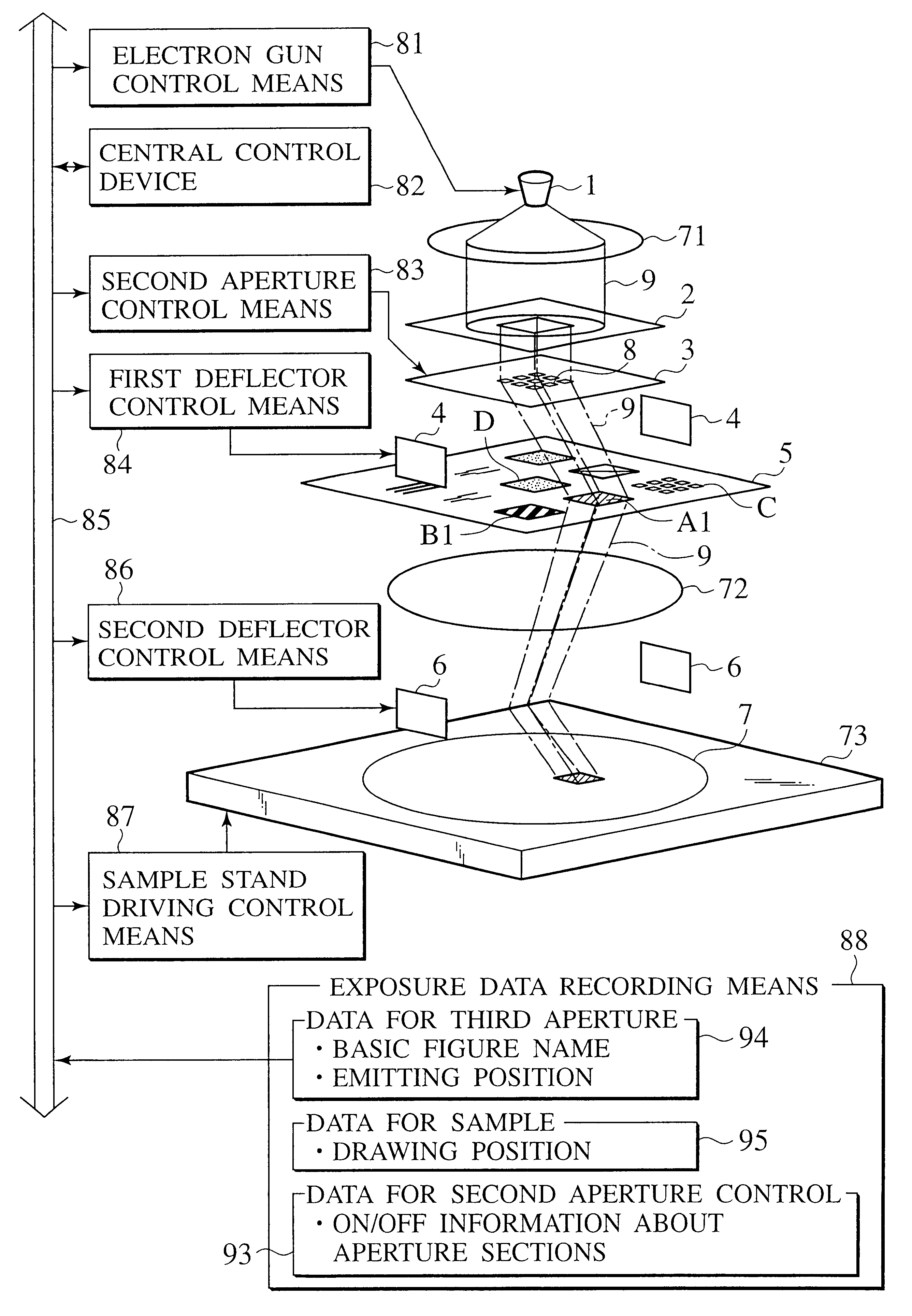
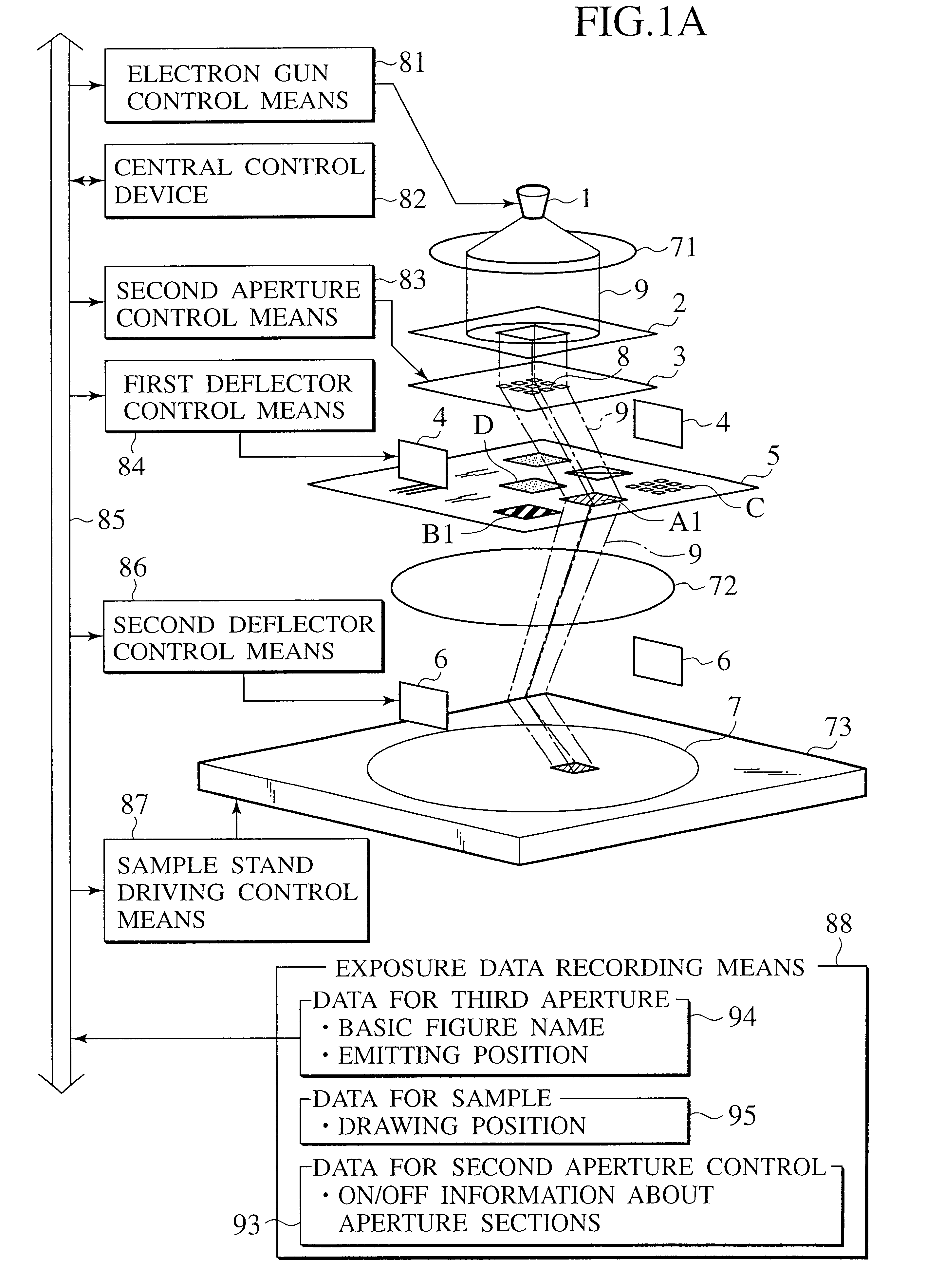
In the third embodiment, the exposure apparatus used in the first embodiment is used. The characteristic of the third embodiment is that a lot of LSI type patterns 126 are arranged on the third aperture array (basic figure aperture array) 101 as shown in FIG. 18A. Here, the LSI type patterns 126 are patterns of parts composing an LSI circuit. The LSI chip is designed so that several hundred kinds of standard cell (SC) patterns are combined according to applications and are arranged. The third embodiment will explain the case where the SC patterns are the type patterns, namely, the basic figure patterns 126.

SC patterns 103 to 105 shown in FIG. 18B are arranged on one basic figure pattern 102 in the plural basic figure patterns 126. FIG. 18B is one example, and a plurality of SC patterns having different forms (functions) are arranged in the ...

fourth embodiment

(Modified Example of Fourth Embodiment)

The modified example of the fourth embodiment will explain the case where the basic figures of the basic figure apertures are oblique wiring patterns.

In the modified example of the fourth embodiment, the exposure apparatus used in the first embodiment is used. The feature of the modified example of the fourth embodiment is that oblique wiring patterns 163 and 164 are arranged on a third aperture array 162 as shown in FIG. 25B. The oblique wiring pattern 163 is an oblique wiring pattern from the upper left to the lower right. The oblique wiring pattern 163 has ten apertures R1 to R10. The oblique wiring pattern 164 is an oblique wiring pattern from the upper right to the lower left. The oblique wiring pattern 164 has ten apertures L1 to L10. The third aperture array 142 shown in FIG. 25B has aperture 145 for a VSB exposure.

Further, aperture sections 161 shown in FIG. 25A are formed on a second aperture array 160 to be used in the modified exampl...


PUM

PropertyMeasurementUnit
acceleration voltageaaaaaaaaaa
widthaaaaaaaaaa
widthaaaaaaaaaa

Abstract

Two or more-staged masks are prepared for a charged beam generating source. One mask has first aperture sections having rectangular apertures arranged into a lattice form, and electrodes which deflects a beam at respective first aperture sections. The other mask has a second aperture section having basic figure apertures for shaping the beam which passes or passed through the first aperture sections. Layout data of a semiconductor apparatus are divided into sizes of the basic figures which take reduction in exposure into consideration so as to be classified according to the basic figures. The beam which is shaped into a form of an overlapped portion of the divided layouts and the classified basic figure is emitted onto a sample.

Description

This application is based upon and claims the benefit of priority from the prior Japanese Patent Applications Nos. P2000-227841 and P2001-222106, filed on Jul. 27, 2000 and Jul. 23, 2001; the entire contents of which are incorporated herein by reference.1. Field of the InventionThe present invention relates to exposure using an electron or ion charged beam. More specifically, the invention relates to exposure of an arbitrary pattern under a condition of constant and periodical arrangement of wirings, standard cells and the like of a semiconductor apparatus.2. Description of the Related ArtAn electron-beam exposure technique enables processing of fine patterns of not more than submicron-meter which cannot be produced by photolithography. For this reason, the electron-beam exposure technique is becoming essential for a semiconductor processing technique which requires refining, high-integration and complication.In variable shaped beam (VSB) exposure which is a typical electron-beam ex...

Claims


Application Information

Patent Timeline
Patent Type & Authority Patents(United States)
IPC IPC(8): G21K1/00G21K1/087H01J37/317G03F1/22G03F7/20H01J37/147H01J37/305H01L21/027
CPCB82Y10/00B82Y40/00G21K1/087H01J37/3174H01J2237/31776
Inventor NAKASUGI, TETSURO
Owner KK TOSHIBA
Why Eureka
Try Eureka