
Automated chemiluminescence analyzer

a chemiluminescence analyzer and automatic technology, applied in the field of instrumental chemiluminescence analysis, can solve the problems of sia in its conventional prior-art configuration disadvantage, and achieve the effect of increasing the collection of ligh

Inactive Publication Date: 2004-04-06
GLOBAL FIA
View PDF11 Cites 29 Cited by
  • Summary
  • Abstract
  • Description
  • Claims
  • Application Information

AI Technical Summary

Benefits of technology

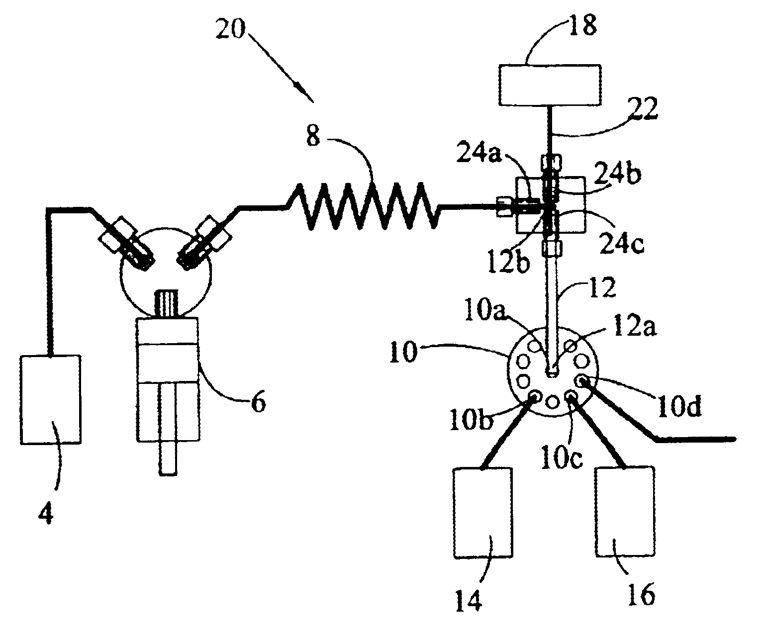
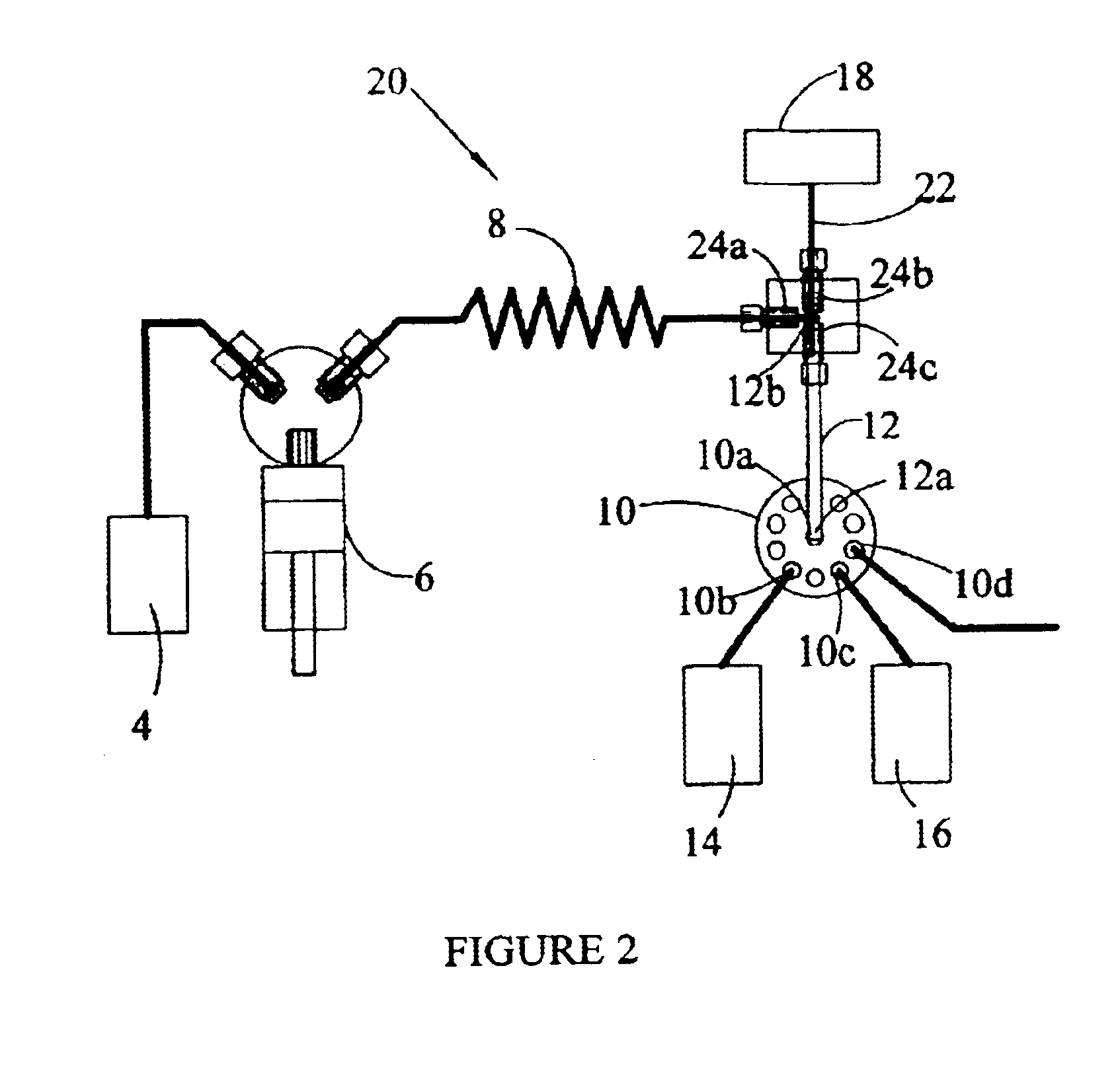
By connecting the first end 12a of the CL flow cell 12 directly to the common aspiration port 10a of the selection valve 10 and the second end 12b to the third port 24c of the T-block 24, as shown in FIG. 2, mixing and chemical reaction of the sample 14 and the reagent 16 are initiated at the entrance 12a of the cell 12, and there is no delay between initiation of CL and detection of the emitted light. Thus, very rapid reactions can be viewed and high sensitivity attained in CL analyses. By aspirating a plurality of alternating zones of sample 14 and reagent 16 into the cell 12, stopping the flow, and collecting and integrating the light generated, even higher sensitivity can be achieved. The number of alternating zones of sample 14 and reagent 16 can vary, from one pair to several pair. The final step is to reverse flow and flush the cell 12 with solvent through a waste outlet port 10d of the selection valve 10, to prepare the chemiluminescence analyzer 20 for the next analysis. Cycle time is short, generally from about five to about sixty seconds.
Preferably, the cell 12 is an LCW cell, in order to provide maximum sensitivity, and the second port 24b of the T-block 24 is optically connected to the detector 18 by an optical fiber 22, or some other suitable interface, such as a window. If an optical fiber is used it is preferable, but not necessary, that it extend into the flow-cell channel in order to increase the collection of light.

Problems solved by technology

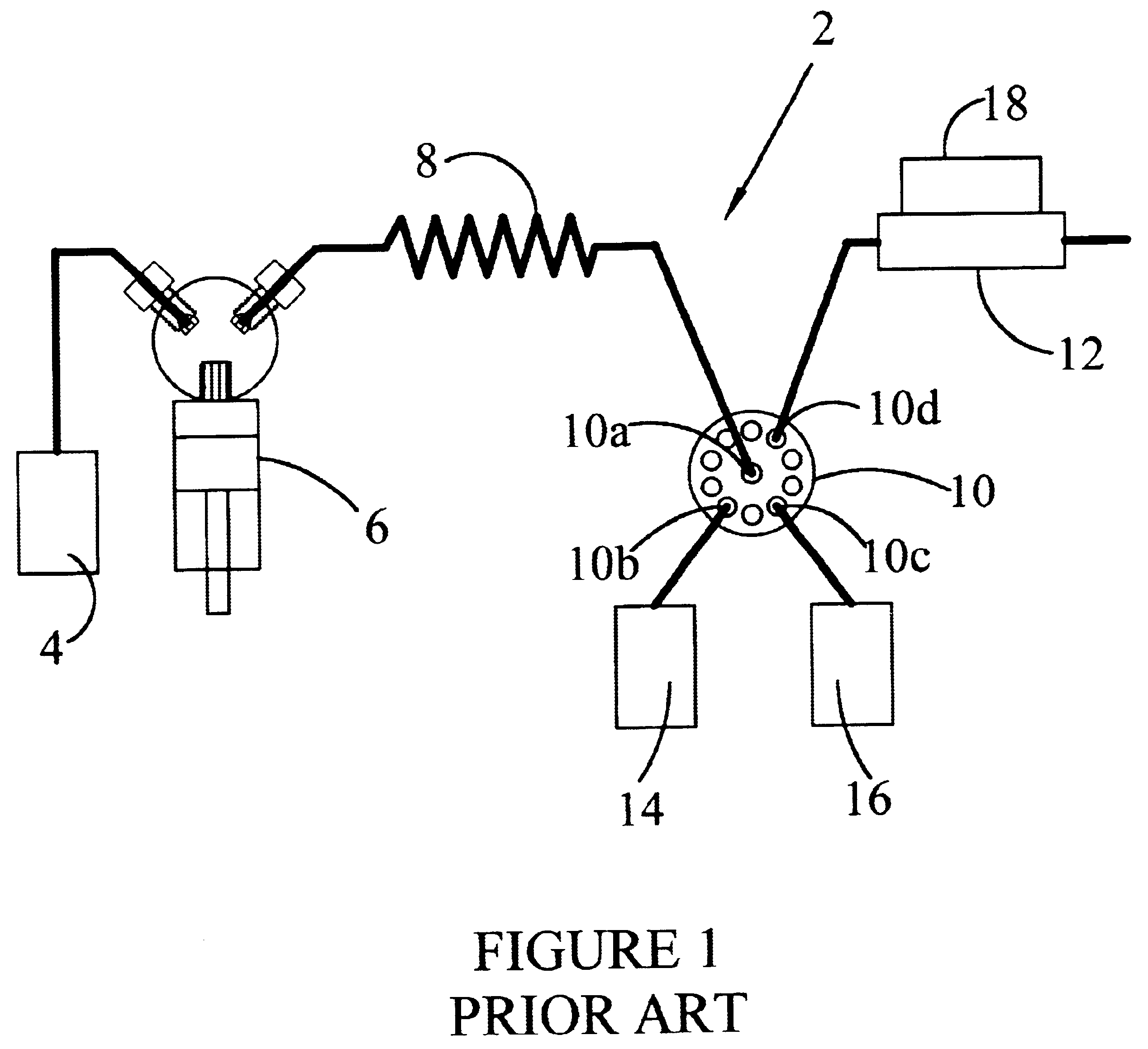
This delay is a disadvantage of SIA in its conventional prior-art configuration when used with rapid CL reactions.

Method used


Image

  • Automated chemiluminescence analyzer
  • Automated chemiluminescence analyzer
  • Automated chemiluminescence analyzer

Examples


Embodiment Construction

The sample 14 was a water solution of 2.61.times.10.sup.-10 molar (M) adenosine triphosphate (ATP). The reagent 16 was Enliten.RTM., a registered trademark of Promega Corporation, a mixture of luciferin and luciferase (L / L) in buffer with stabilizers, purchased from Promega Corp., 2800 Woods Hollow Road, Madison, Wis. 57711. The ATP L / L reaction is a well-known chemiluminescence reaction that is used in a number of different analytical applications. The cell 12 was an LCW cell made of an amorphous fluoropolymer which is a copolymer of tetrafluoroethylene and perfluoro-2,2-dimethyl-1,3-dioxane, marketed under the registered trademark TEFLON AF.RTM. by E. I. Dupont de Nemours, a corporation of Wilmington, Del. The cell 12 had an internal diameter (ID) of seven one-hundredths of an inch (in), and a length of eight centimeters (cm). The detector 18 was a photomultiplier tube (PMT). A thin frit having a pore size of from about ten to about twenty microns was placed at the first end 12a o...


PUM

PropertyMeasurementUnit
lengthaaaaaaaaaa
pore sizeaaaaaaaaaa
chemiluminescence analyzeraaaaaaaaaa

Abstract

An automated chemiluminescence analyzer. A multiport selection valve has a common aspiration port for carrier solvent, sample, and reagent. A bi-directional pump is connected to the selection valve. A chemiluminescence cell is positioned between the selection valve and a T-block. One end of the cell is connected to the common port of the selection valve, and the other end is connected to the T-block. The T-block has a port connected to the pump, another port which communicates with the detector, and a third port connected to the other end of the cell. This unique arrangement enables the chemiluminescence cell to function as a chemical reactor, thus eliminating any delay between initiation and detection of emitted radiation, so that very rapid reactions can be viewed and high sensitivity attained.

Description

BACKGROUND OF INVENTIONThe present invention relates to instrumental chemical analysis. More particularly, the invention relates to instrumental chemiluminescence analysis.Chemiluminescence (CL) is the generation of light from chemical reactions. CL processes have attracted mankind's attention for centuries. Aristotle wrote the first known report on the phenomenon when he noted weak light emitted by dead fish and fungi. The term chemiluminescence was first defined by Wiedemann in 1888 as light emitted from chemical reactions.Many CL reactions are now well known. Early studies of CL focused primarily on the chemistry and mechanisms of CL reactions. In the early 1960's analytical applications of CL reactions began to appear in the literature. Since then, CL analytical methods have grown substantially due to the advantages of low detection limits, wide linear dynamic ranges, and fast response.The early analytical applications involved manual techniques for mixing reagent and sample, an...

Claims


Application Information

Patent Timeline
Patent Type & Authority Patents(United States)
IPC IPC(8): G01N21/76
CPCG01N21/76
Inventor OLSON, DON C.
Owner GLOBAL FIA
Learn More