Electromagnetic shielding plate and method for producing the same

a technology shielding plate, which is applied in the field of electromagnetic shielding plate, can solve the problems of easy expansion and contraction of the mesh, and increased difficulty in handling the mesh

Inactive Publication Date: 2004-04-06
SUMITOMO RUBBER IND LTD
View PDF12 Cites 34 Cited by
  • Summary
  • Abstract
  • Description
  • Claims
  • Application Information

AI Technical Summary

Benefits of technology

The present invention has been completed based on the finding that an electromagnetic shielding plate having good electromagnetic shielding properties and also high visibility and strength can be easily produced, even if it has a large size, when a geometric pattern is formed on a glass substrate by printing the pattern with a paste containing an inorganic filler selected from the group consisting of metals and metal oxides and a glass frit having a softening point of about 200 to 700.degree. C., baking the pattern, and optionally forming a metal layer on the geometric pattern by wet plating.

Problems solved by technology

However, the electromagnetic shielding plate comprising the conductive mesh has a problem that the handling of the mesh is not easy, since the conductive mesh, which is a knit, easily expands and contracts when the plate is produced.
Such a conductive mesh more easily expands and contracts, so that the handling thereof becomes more difficult.
In addition, such a conductive mesh, which easily expands and contracts, has a problem that it tends to suffer from the change of the lattice distance and the deformation of the lattice pattern, when it is adhered to the transparent substrate.
Thus, such an electromagnetic shielding plate may not be easily produced.
Thus, it does not have sufficient electromagnetic shielding properties.
Furthermore, the adhesion of the lattice formed from such a conductive paint to a glass substrate is insufficient.
In addition, defects such as creasing may appear in handing.
Furthermore, when the geometric pattern is formed on the glass substrate with the currently used paste, the adhesion of the pattern to the substrate is insufficient.
The adhesion of such a geometric pattern to the glass substrate is also insufficient.
JP-A-10-64435 and JP-2001-6435A disclose the addition of glass powder to a paste, which is used to form an internal electrode of a plasma display panel, but they do not disclose the use of glass powder in an electromagnetic shielding plate which requires high visibility and good electromagnetic shielding properties.

Method used


Image

  • Electromagnetic shielding plate and method for producing the same
  • Electromagnetic shielding plate and method for producing the same

Examples


example 1

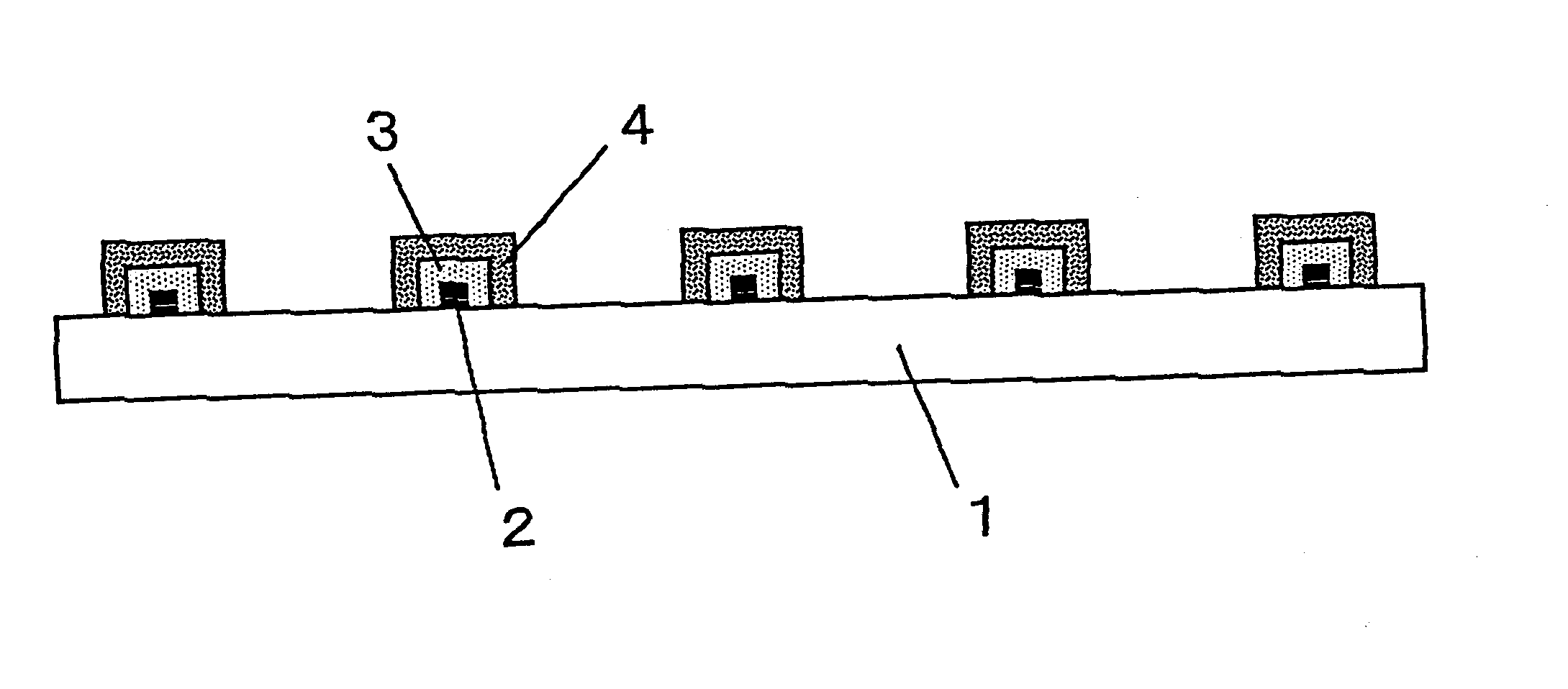
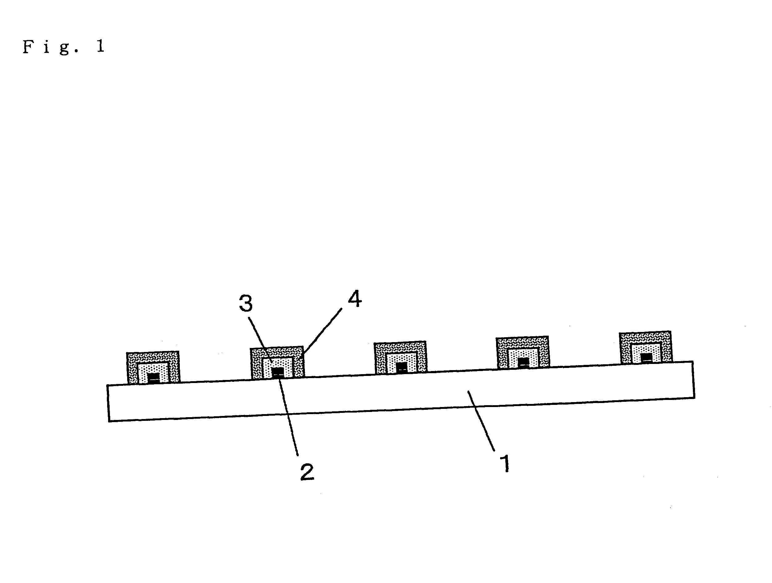
On a soda-lime glass substrate having a size of 300 mm.times.400 mm and a thickness of 3 mm, a lattice-form pattern having a line distance of 250 .mu.m and a line width of 27 .mu.m was formed with Paste A by a plate offset printing process.

The glass substrate carrying the printed pattern was baked in an air at 700.degree. C. for 5 minutes, and then quenched by blowing the air. With such treatments, the pattern was firmly adhered to the substrate, and the substrate glass was tempered.

The polyester resin contained in Past A alone was subjected to a thermogravimetry by heating the resin at 700.degree. C. for 5 minutes. These heating conditions are comparable to the baking conditions above. The polyester resin was burnt out almost completely.

The tempered glass substrate carrying the baked pattern was degreased by dipping it in a 50 g / L solution of a degreasing agent ("ACE CLEAN A-220" manufactured by Okuno Chemical Co., Ltd.) kept at 50.degree. C. for 10 minutes, and then dipped in a 10...

example 2

A pattern was formed on a glass substrate by a plate offset printing process, and then the pattern was baked and the glass substrate was tempered in the same manners as in Example 1 except that Paste B was used in place of Paste A. The ethylcellulose resin contained in Paste B alone was subjected to a thermogravimetry by heating the resin at 700.degree. C. for 5 minutes. The ethylcellulose resin was burnt out almost completely.

Thereafter, the substrate carrying the formed pattern was subjected to the electroless plating with copper, the electroplating with copper and anodization in the same manners as those in Example 1 to make the surface of the pattern black.

The results of the evaluations of this electromagnetic shielding plate are shown in Table 1.

example 3

A pattern was formed on a glass substrate by a plate offset printing process in the same manner as in Example 1 except that Paste C was used in place of Paste A. Then, the pattern was baked at 450.degree. C. for 1 hour. The polyester resin contained in Paste C alone was subjected to a thermogravimetry by heating the resin at 450.degree. C. for 5 minutes. The residual amount of the polyester resin after baking was 5% of the weight of the resin before baking.

Thereafter, the substrate carrying the formed pattern was subjected to the electroless plating with copper, the electroplating with copper and anodization in the same manners as those in Example 1 to make the surface of the pattern black.

The results of the evaluations of this electromagnetic shielding plate are shown in Table 1.

The electromagnetic shielding property of the electromagnetic shielding plate was evaluated. The results are 53 dB at 50 MHz, 53 dB at 100 MHz, and 60 dB at 300 MHz.


PUM

PropertyMeasurementUnit
softening pointaaaaaaaaaa
widthaaaaaaaaaa
softening pointaaaaaaaaaa

Abstract

An electromagnetic shielding plate having a glass substrate and a geometric pattern formed on the substrate, in which the geometric pattern contains (a) an inorganic filler selected from the group consisting of metals and metal oxides, and (b) a glass component having a softening point of about 200 to 700° C.

Description

The present invention relates to an electromagnetic shielding plate and a method for producing the samePRIOR ARTAn electromagnetic shielding plate is used, for example, as a front filter to be attached to a display, since it can shield electromagnetic waves leaking from the display. The electromagnetic shielding plate used as the front filter should have a property not to decrease the visibility of a display screen of the display in addition to the property to shield the electromagnetic waves. As such an electromagnetic shielding plate, a shielding plate comprising a transparent substrate and a conductive mesh attached to the substrate is known. The conductive mesh is a mesh of conductive fibers knit in a lattice form, and a conductive fiber comprising organic fiber (e.g. polyester fiber, etc.) having a metal thin layer formed on the surface thereof is used.However, the electromagnetic shielding plate comprising the conductive mesh has a problem that the handling of the mesh is not ...

Claims


Application Information

Patent Timeline
Patent Type & Authority Patents(United States)
IPC IPC(8): C03C17/00H05K9/00G09F9/00
CPCC03C17/006C03C17/007H05K9/0096C03C2217/40C03C2217/452C03C2217/475C03C2217/479C03C2217/485H05K9/00
Inventor UEDA, KAYOKOYAMANE, HISANORIKONDO, YASUHIKOSUGIYA, MAKOTO
Owner SUMITOMO RUBBER IND LTD
Why Eureka
Try Eureka