Ion-source neutralization with a hot-filament cathode-neutralizer

a technology of neutralizer and hot filament, which is applied in the direction of discharge tube main electrodes, incadescent cooling arrangements, machines/engines, etc., can solve the problems of more heating at the end, more rapid failure of hot filament, and difficulty in obtaining second kind of neutralization, so as to maximize the hot filament life and minimize overheating. , the effect of simple and reliabl

Inactive Publication Date: 2004-04-20
KAUFMAN & ROBINSON
View PDF10 Cites 25 Cited by
  • Summary
  • Abstract
  • Description
  • Claims
  • Application Information

AI Technical Summary

Benefits of technology

Another object of the present invention is to provide such an apparatus that provides current neutralization without the complications or operating problems of sensing, comparing, and controlling two separate currents.
Yet another object of the invention is to provide such an apparatus that is simple, economical, and reliable.
Still another object of the present invention is to provide such an apparatus that maximizes the hot-filament lifetime by minimizing the over-heating of the hot-filament cathode-neutralizer used to provide a margin in electron-emission capability.

Problems solved by technology

A direct current could be used to heat either the hot-filament discharge-chamber cathode or the hot-filament cathode-neutralizer, but the use of a direct current results in the electron emission always adding to the heater current at one end of the hot filament, resulting in more heating at that end, and a more rapid failure of the hot filament than if an alternating current had been used to average the heating effects at the two ends of the hot filament.
The second kind of neutralization is more difficult to obtain and is called "current neutralization."
The accelerator current is normally small compared to either the beam current or the electron emission from the cathode-neutralizer, so that there is usually no practical significance of this inclusion.
In short, the larger the target surface that is electrically isolated from ground, the greater the variation in target potential for a given departure from current neutralization, and the greater the likelihood of electrostatic charging damage.
There is, however, no apparent reason it could not be used in industrial applications.

Method used


Image

  • Ion-source neutralization with a hot-filament cathode-neutralizer
  • Ion-source neutralization with a hot-filament cathode-neutralizer
  • Ion-source neutralization with a hot-filament cathode-neutralizer

Examples


Embodiment Construction

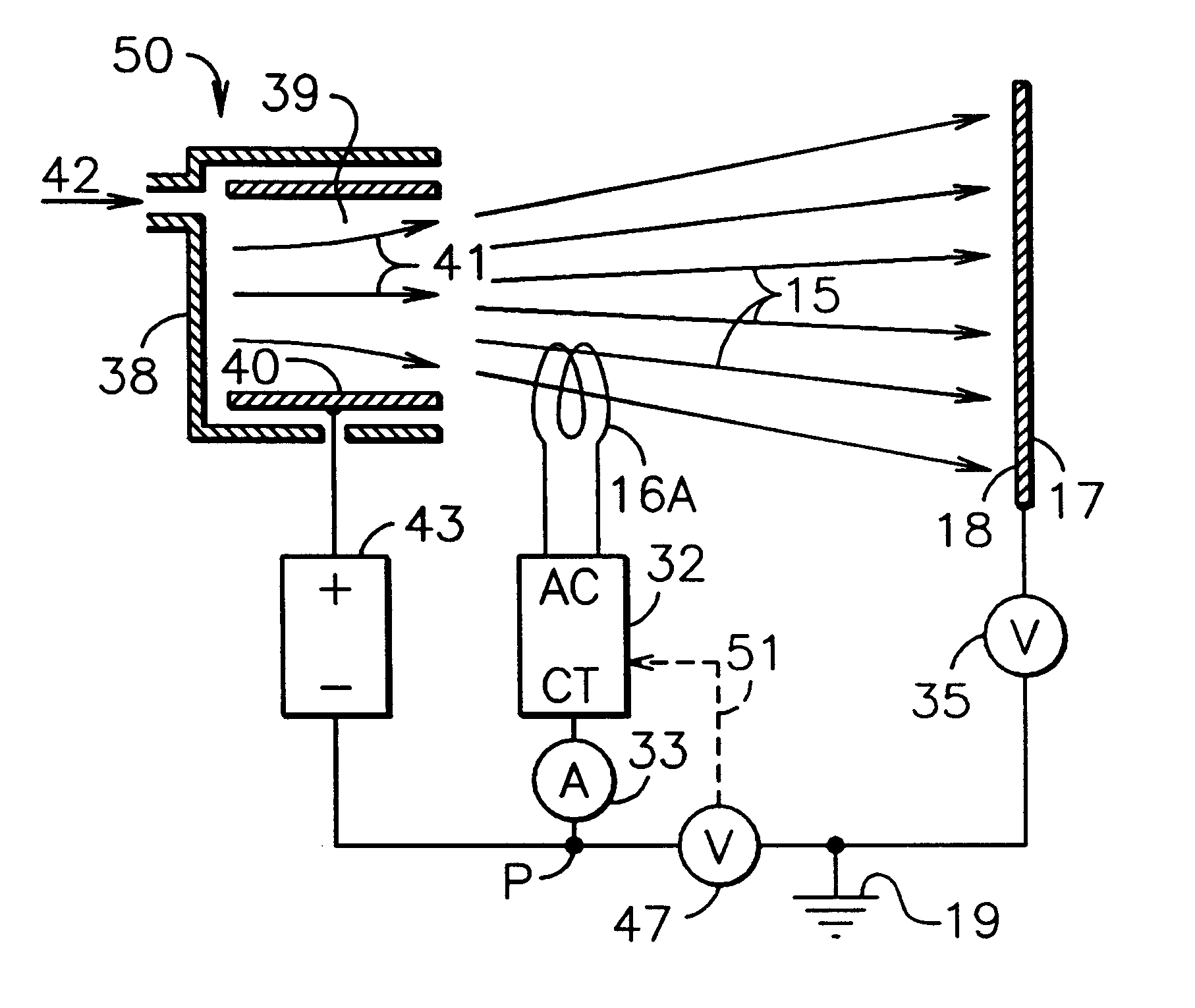
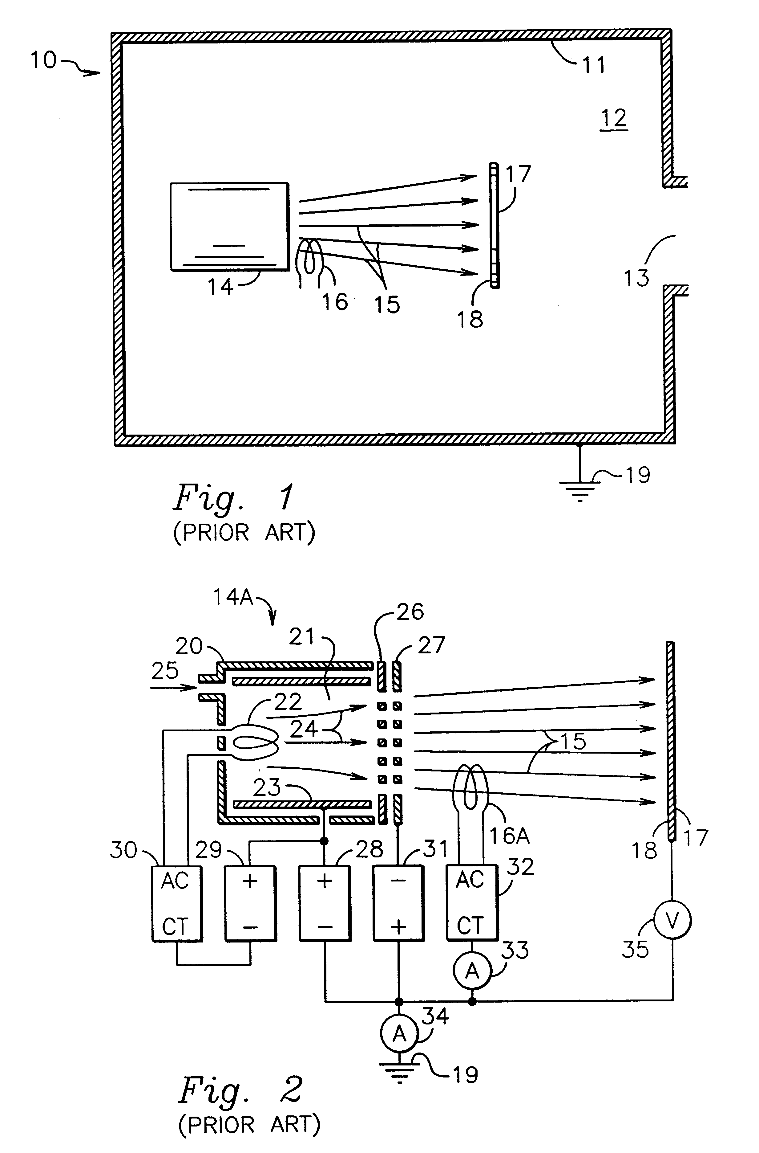
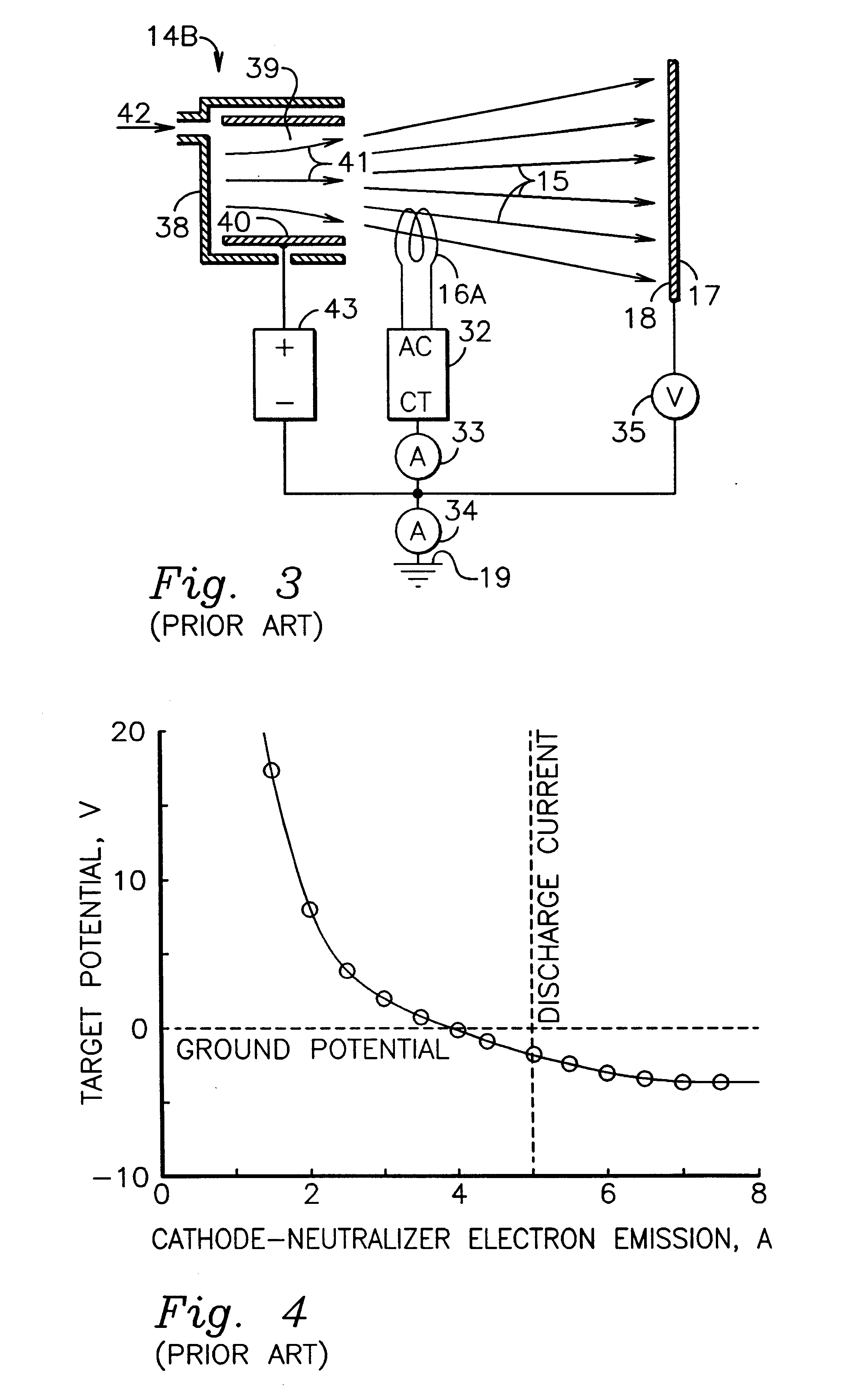
Referring to FIG. 9, there is shown ion-source apparatus 50 that is an embodiment of the present invention wherein the ion source is of the gridless type. As in discussions of prior art, the gridless ion source in FIG. 9 could be of either the end-Hall or the closed-drift types. This apparatus is generally similar to the ion source apparatus 14B in FIG. 3, except that the electron emission is self-regulating in a manner previously only obtained with hollow-cathode cathode-neutralizers.

Operation of the ion source is generally similar to that described for FIG. 3. Gridless ion source 50 has outer enclosure 38 that surrounds volume 39. Within this volume there are anode 40 and magnetic field 41. Electrons emitted by cathode-neutralizer 16A are constrained by the magnetic field and reach the anode only as the result of a variety of collision processes. Some of these collisions are with ionizable gas 42 introduced into volume 39 and generate ions. Some of the ions generated are accelerat...


PUM


Abstract

In accordance with one embodiment of the present invention, the ion-beam apparatus takes the form of a gridless ion source with a hot-filament cathode-neutralizer, in which the hot filament is heated with a current from the cathode-neutralizer heater. The cathode-neutralizer is connected to the negative terminal of the discharge supply for the gridless ion source. This connection is substantially isolated from ground (the potential of the surrounding vacuum chamber, which is usually at earth ground) and its potential is measured relative to ground. The heater current to the cathode-neutralizer is controlled by adjusting it so as to maintain this potential in a narrow operating range. This control can be manual or automatic.

Description

This invention relates generally to ion and plasma sources, and more particularly it pertains to the neutralization of the ion beams from such sources with some or all of the electrons from hot-filament cathode-neutralizers.Industrial ion sources are used for etching, deposition and property modification, as described by Kaufman, et al., in the brochure entitled Characteristics, Capabilities, and Applications of Broad-Beam Sources, Commonwealth Scientific Corporation, Alexandria, Va. (1987).Both gridded and gridless ion sources are used in these industrial applications. The ions generated in gridded ion sources are accelerated electrostatically by the electric field between the grids. Only ions are present in the region between the grids and the magnitude of the ion current accelerated is limited by space-charge effects in this region. Gridded ion sources are described in an article by Kaufman, et al., in the AIAA Journal, Vol. 20 (1982), beginning on page 745. The particular source...

Claims


Application Information

Patent Timeline
Patent Type & Authority Patents(United States)
IPC IPC(8): F03H1/00
CPCH01J27/14
Inventor KAUFMAN, HAROLD R.KAHN, JAMES R.ZHURIN, VIACHESLAV V.
Owner KAUFMAN & ROBINSON
Why Eureka
Try Eureka