Ejector decompression device with throttle controllable nozzle

a controllable nozzle and ejector technology, which is applied in the direction of refrigeration components, machines/engines, lighting and heating apparatus, etc., can solve the problems of insufficient increase of the pressure of refrigerant to be sucked to the compressor by the ejector, and inability to satisfactorily reduce the motive power consumed by the compressor

Inactive Publication Date: 2004-05-04
DENSO CORP
View PDF21 Cites 27 Cited by
  • Summary
  • Abstract
  • Description
  • Claims
  • Application Information

AI Technical Summary

Benefits of technology

It is a second object of the present invention to variably control a throttle degree of a nozzle of the ejector decompression device without largely reducing ejector efficiency .eta.e of the ejector decompression device.
According to the present invention, an ejector decompression device for a refrigerant cycle includes a nozzle for decompressing and expanding refrigerant flowing from a radiator by converting pressure energy of refrigerant to speed energy of the refrigerant, a pressure-increasing portion that is disposed to increase a pressure of refrigerant by converting the speed energy of refrigerant to the pressure energy of refrigerant while mixing refrigerant injected from the nozzle and refrigerant sucked from an evaporator of the refrigerant cycle, and a needle valve disposed to be displaced in a refrigerant passage of the nozzle in an axial direction of the nozzle for adjusting an opening degree of the refrigerant passage of the nozzle. Here, the refrigerant passage is defined by an inner wall of the nozzle. Further, the nozzle includes a throat portion having a cross-sectional area that is smallest in the refrigerant passage of the nozzle, and an expansion portion in which the cross-sectional area is increased from the throat toward downstream in a refrigerant flow. In the ejector decompression device, the needle valve and the inner wall of the nozzle are provided to have predetermined shapes so that refrigerant flowing into the nozzle is decompressed to a gas-liquid two-phase state at upstream from the throat portion in the refrigerant flow. In the present invention, because refrigerant is decompressed to the gas-liquid state at upstream from the throat portion, refrigerant bubbles are generated, and a mass density of the refrigerant is reduced. Accordingly, the cross-sectional area of the refrigerant passage is relatively reduced in the nozzle. Thus, the flow amount of refrigerant can be adjusted, and the refrigerant passage can be prevented from being throttled more than a necessary degree. As a result, ejector efficiency .eta.e can be prevented from being largely reduced in the ejector decompression device having the nozzle where the opening degree of the refrigerant passage can be variably controlled.
Alternatively, the needle valve is disposed in the refrigerant passage of the nozzle to define a throttle portion having a cross-sectional area that is smallest in a space between the needle valve and the inner wall of the nozzle, and the throttle portion is positioned upstream from the throat portion in the refrigerant flow. Therefore, rectified refrigerant with a small disturbance can pass through the throat portion, and is sufficiently accelerated more than the sound speed while flowing through the extension portion. Because the refrigerant can be accurately sufficiently accelerated in the nozzle, the ejector efficiency can be effectively improved.

Problems solved by technology

However, when energy converting efficiency of the ejector, that is, ejector efficiency .eta.e is reduced, the pressure of refrigerant to be sucked to the compressor cannot be sufficiently increased by the ejector.
In this case, the motive power consumed by the compressor cannot be satisfactorily reduced.

Method used


Image

  • Ejector decompression device with throttle controllable nozzle
  • Ejector decompression device with throttle controllable nozzle
  • Ejector decompression device with throttle controllable nozzle

Examples


first embodiment

(First Embodiment)

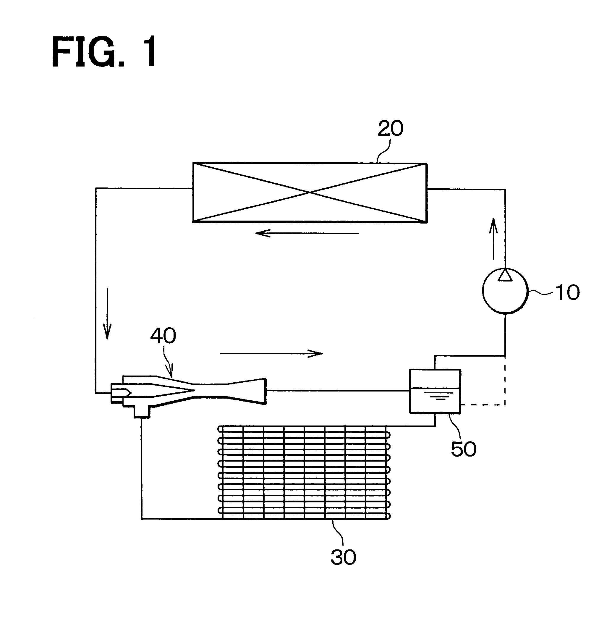
In the first embodiment, as shown in FIG. 1, an ejector for an ejector cycle is typically used for a heat pump cycle for a water heater. In the ejector cycle, the ejector is used as a decompression device for decompressing refrigerant. In the heat pump cycle shown in FIG. 1, a compressor 10 sucks and compresses refrigerant, and a radiator 20 cools the refrigerant discharged from the compressor 10. Specifically, the radiator 20 is a high-pressure heat exchanger that heats water for the water heater by heat-exchange between the refrigerant flowing from the compressor 10 and the water. The compressor 10 is driven by an electric motor (not shown), and a rotation speed of the compressor 10 can be controlled. A flow amount of refrigerant discharged from the compressor 10 is increased by increasing the rotational speed of the compressor 10, thereby increasing heating performance of the water in the radiator 20. On the contrary, the flow amount from the compressor 10 is re...

second embodiment

(Second Embodiment)

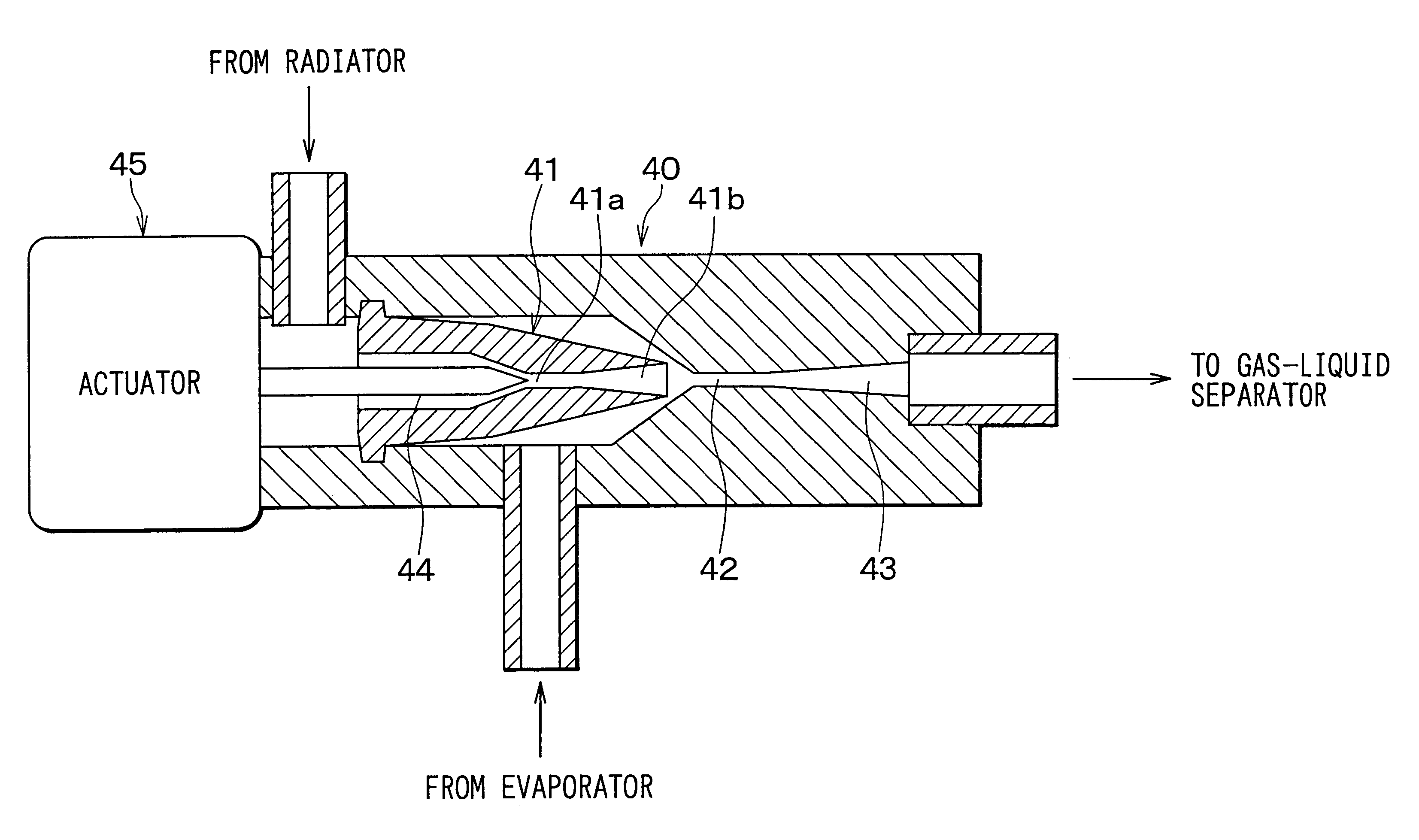
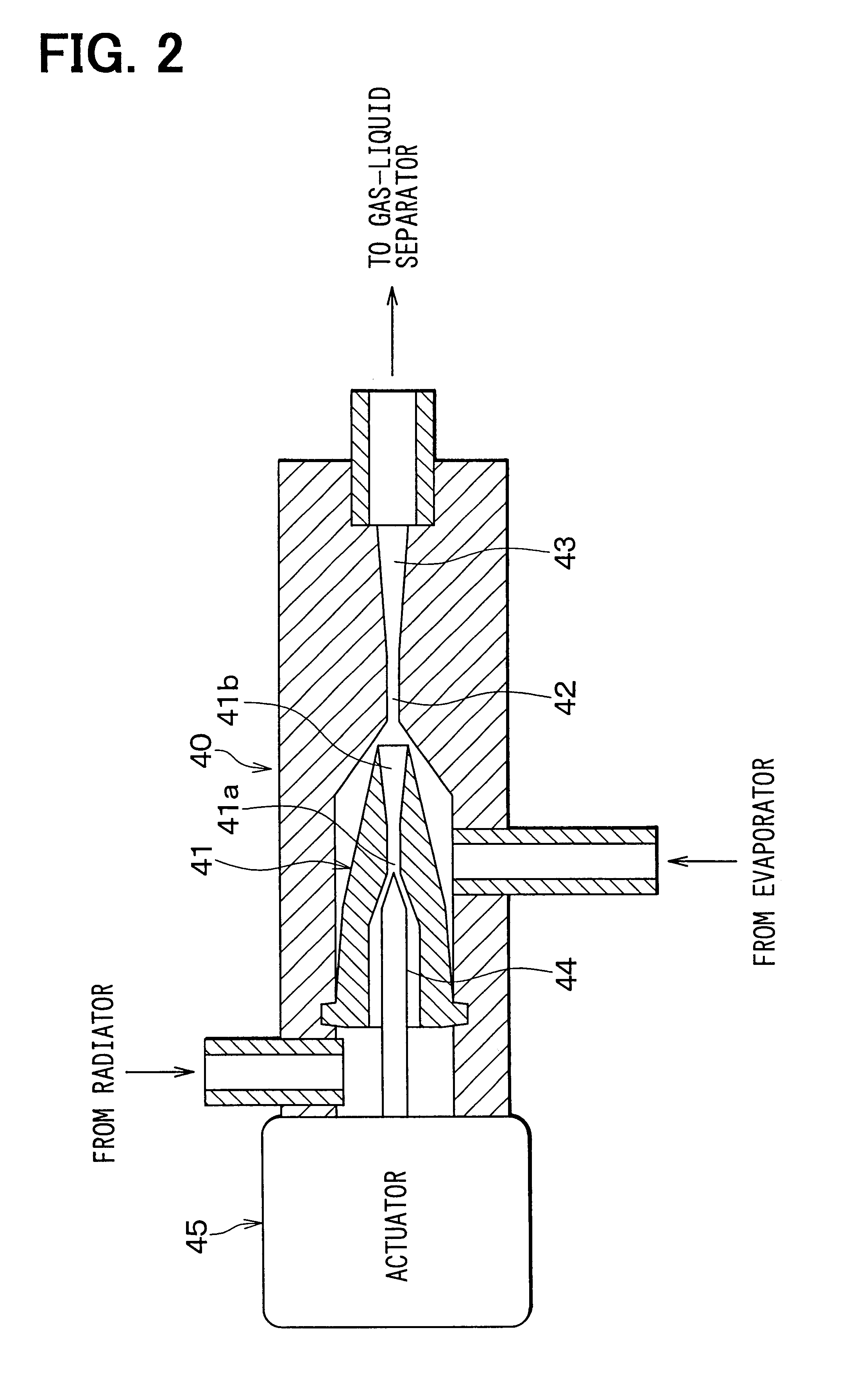
In the above-described first embodiment, as shown FIG. 3B, the inner wall surface of the nozzle 41 are formed into the two-step taper shape to have two taper angles .alpha.1, .alpha.2, so that the inner radial dimension d1 is reduced toward the throat portion 41a. However, in the second embodiment, as shown in FIG. 8, the inner wall surface has a taper angle gradually reduced toward the throat portion 41a, and is formed in a non-step taper shape so that the inner radial dimension d1 is reduced toward the throat portion 41a. Accordingly, the cross-sectional area of the refrigerant passage is smoothly and continuously changed in the nozzle 41, and turbulence can be further restricted from being generated in the refrigerant stream.

In the second embodiment, the other parts are similar to those of the above-described first embodiment. Accordingly, similarly to the first embodiment, the refrigerant is decompressed to the gas-liquid two-phase state at an upstream side of...

third embodiment

(Third Embodiment)

In the third embodiment, as shown in FIGS. 9A, 9B, the inner wall surface of the nozzle 41 is formed as a smoothly curved surface so that refrigerant is decompressed to the gas-liquid phase state at upstream from the throat portion 41a. In FIGS. 9A, 9B, 41d indicates an upstream area portion of the throat portion 41a, where the inner radial dimension d1 is reduced toward the throat portion 41a. Further, the nozzle 41, the mixing portion 42 and the diffuser 43 are set in the ejector 40 to have the sectional areas shown in FIG. 9B.

In the third embodiment, the other parts are similar to those of the above-described first embodiment. Accordingly, similarly to the first embodiment, the refrigerant is decompressed to the gas-liquid two-phase state at an upstream side of the throat portion 41a.

Although the present invention has been fully described in connection with the preferred embodiments thereof with reference to the accompanying drawings, it is to be noted that vari...


PUM


Abstract

An ejector for a refrigerant cycle includes a nozzle having therein a refrigerant passage, and a needle valve provided in the refrigerant passage of the nozzle upstream from a throat portion of the nozzle. The needle valve is disposed in the nozzle to define therebetween a throttle portion that is positioned upstream from the throat portion. A top end portion of the needle valve and an inner wall of the nozzle are formed, so that refrigerant is decompressed to a gas-liquid two-phase state at upstream of the throat portion. Accordingly, a throttle degree of the nozzle can be variably controlled while ejector efficiency is not deteriorated.

Description

This application is related to and claims priority from Japanese Patent Applications No. 2002-30924 filed on Feb. 7, 2002 and No. 2002-182872 filed on Jun. 24, 2002, the contents of which are hereby incorporated by reference.1. Field of the InventionThe present invention relates to an ejector decompression device for a vapor compression refrigerant cycle. More specifically, the present invention relates to an ejector with a throttle controllable nozzle in which a throttle degree can be controlled.2. Description of Related ArtIn an ejector cycle, pressure of refrigerant to be sucked into a compressor is increased by converting expansion energy to pressure energy in a nozzle of an ejector, thereby reducing motive power consumed by the compressor. Further, refrigerant is circulated into an evaporator by using a pumping function of the ejector. However, when energy converting efficiency of the ejector, that is, ejector efficiency .eta.e is reduced, the pressure of refrigerant to be suck...

Claims


Application Information

Patent Timeline
Patent Type & Authority Patents(United States)
IPC IPC(8): F04F5/46F04F5/04F04F5/00F25B41/00F25B9/00F25B1/00F25B41/06
CPCF04F5/04F04F5/461F25B41/00F25B9/008F25B2309/061F25B2341/0012F25B2341/0013F25B2500/01
Inventor SAKAI, TAKESHINOMURA, SATOSHITAKEUCHI, HIROTSUGU
Owner DENSO CORP
Why Eureka
Try Eureka