Signal strength detecting device with little temperature dependence

a signal strength and temperature dependence technology, applied in the direction of transmission monitoring, instruments, electric/magnetic computing, etc., can solve the problems of reducing the gain g of the differential amplifier 3-5, unable to amplify the received signal to a desired level, and hindering the detection of the signal strength of the received signal

Inactive Publication Date: 2004-05-04
RENESAS TECH CORP
View PDF16 Cites 12 Cited by
  • Summary
  • Abstract
  • Description
  • Claims
  • Application Information

AI Technical Summary

Problems solved by technology

However, this will reduce the gain G of the differential amplifiers 3-5, making it impossible to amplify the received signal to a desired level.
This presents a problem of hindering accurate detection of the signal strength of the received signal.

Method used


Image

  • Signal strength detecting device with little temperature dependence
  • Signal strength detecting device with little temperature dependence
  • Signal strength detecting device with little temperature dependence

Examples


embodiment 1

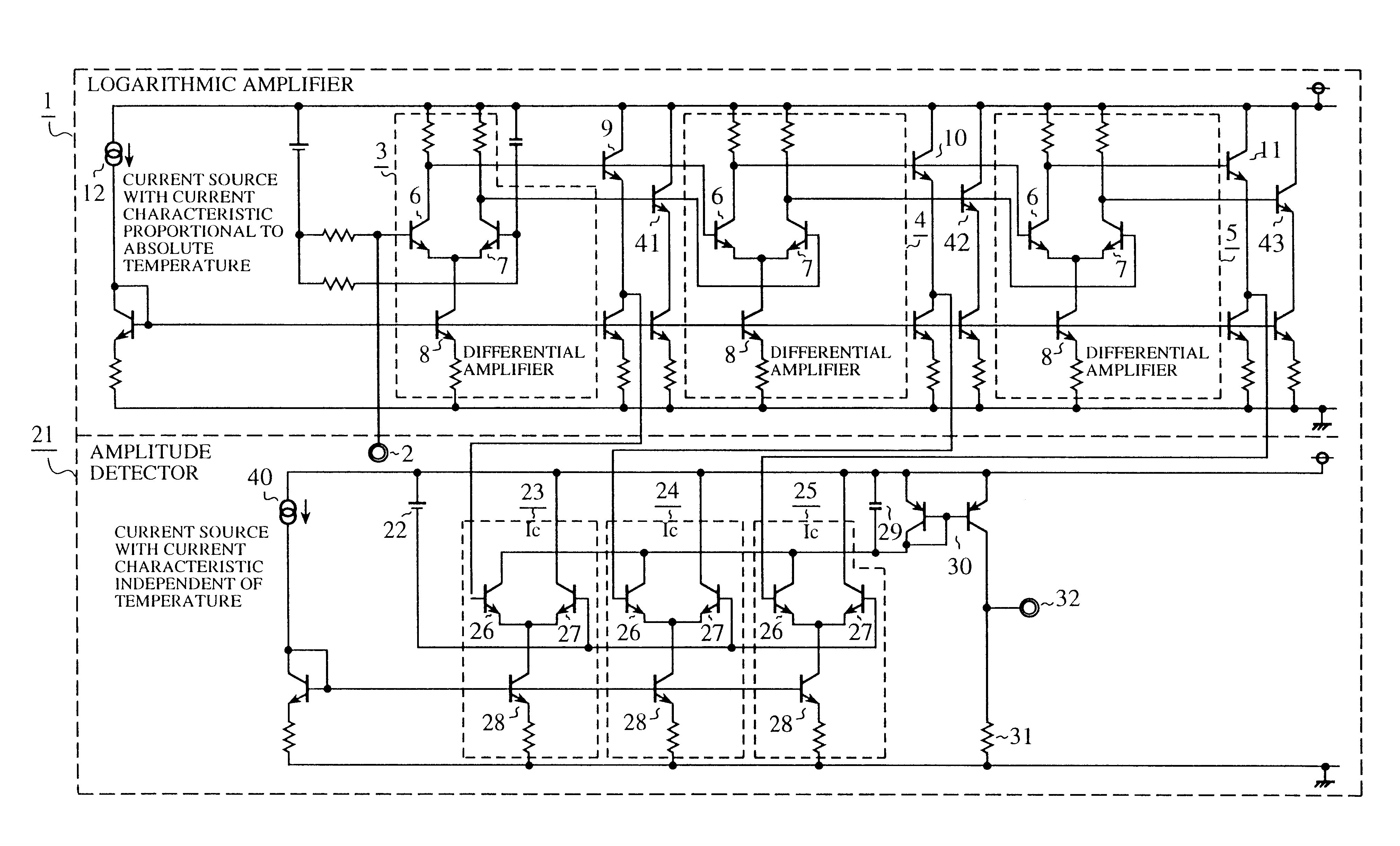
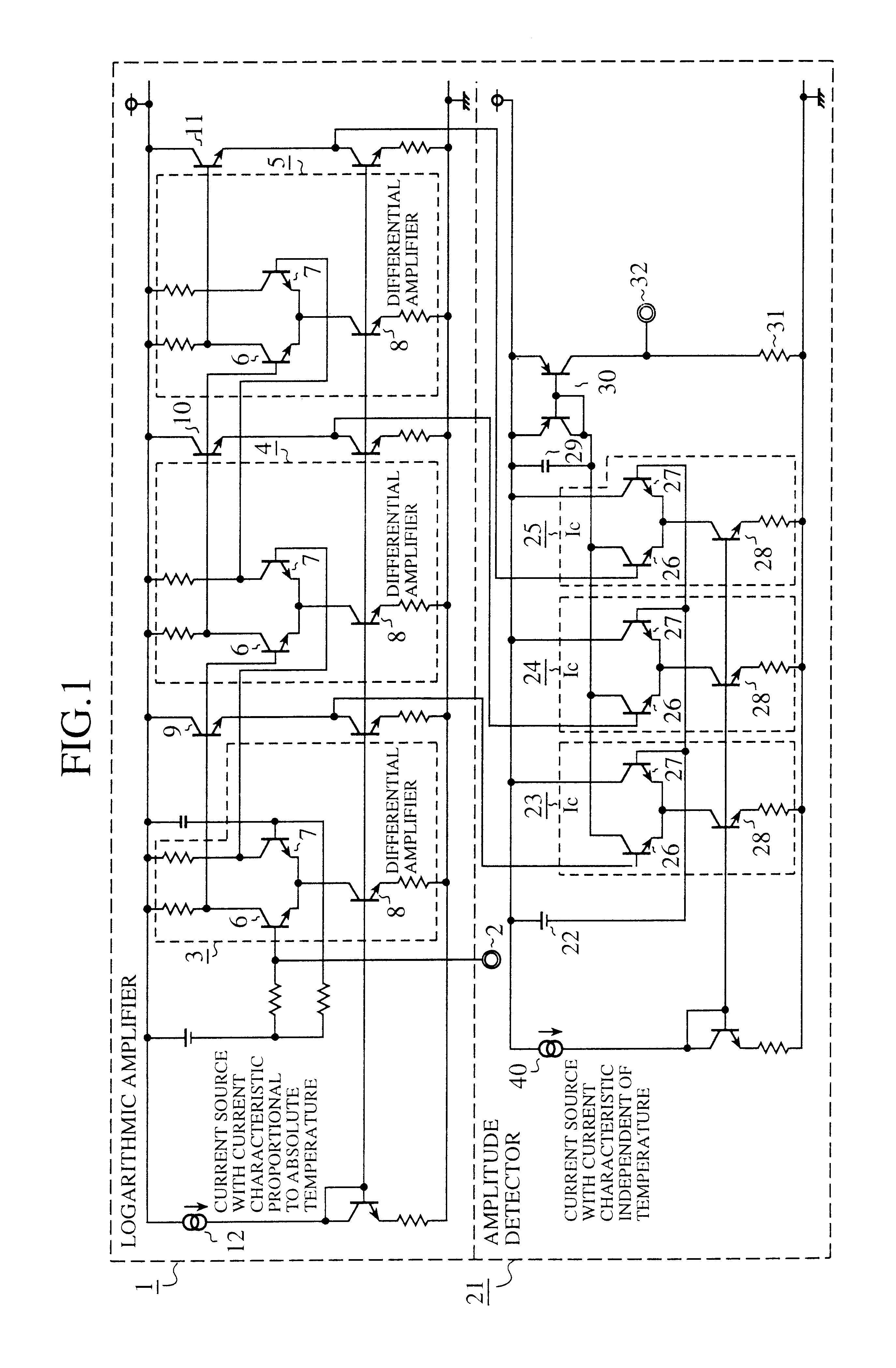
FIG. 1 is a circuit diagram showing the signal strength detecting device in accordance with the present invention. In FIG. 1, the reference numeral 1 designates a logarithmic amplifier for amplifying a signal received by an antenna; 2 designates an input terminal for supplying the signal received by the antenna; 3-5 each designate a differential amplifier for amplifying the received signal supplied from the input terminal 2; 6-8 each designate a transistor constituting the differential amplifiers 3-5; 9-11 each designates an emitter follower for regulating the DC level of the received signal amplified by the differential amplifiers 3-5; and 12 designates a current source for biasing the logarithmic amplifier 1. The current source 12 is a constant current source whose current is proportional to the absolute temperature.

The reference numeral 21 designates an amplitude detector for detecting the signal strength of the received signal by comparing the received signal whose DC level is r...

embodiment 2

FIG. 3 is a circuit diagram showing an embodiment 2 of the signal strength detecting device in accordance with the present invention. In FIG. 3, the same reference numerals designate the same or like portions to those of FIG. 1, and the description thereof is omitted here.

Reference numerals 41-43 each designates an emitter follower for regulating the DC level of the received signal amplified by the differential amplifiers 3-5.

Next, the operation of the present embodiment 2 will be described.

The emitter followers 9-11 are each connected to a first one of the two outputs of each of the differential amplifiers 3-5 in the foregoing embodiment 1, and the two outputs of each of the differential amplifiers 3-5 are unbalanced in this case. This can reduce a power supply rejection ratio (PSRR), and hence is likely to increase power supply noise placed on signal lines.

Therefore, when the power supply noise is large and the signal level is low, the received signal is likely to be buried in the...

embodiment 3

Although the emitter followers 41-43 are connected to the second outputs of the differential amplifiers 3-5 in the foregoing embodiment 2, only the emitter follower 41 can be connected to the second output of the differential amplifier 3 without connecting any emitter follower to the second outputs of the differential amplifiers 4 and 5 as shown in FIG. 5.

More specifically, since the differential amplifier 3, the initial stage amplifier, handles the minute received signal, it is connected to the emitter follower 41 to improve the PSRR. However, since the differential amplifiers 4 and 5, the second and the following stage amplifiers, handle the received signal amplified to some extent by the differential amplifier 3, they will not significantly degrade the PSRR even without the emitter followers 42 and 43.

In view of this, the emitter follower 41 is connected to only the second output of the differential amplifier 3 in the present embodiment 3. This enables the current consumption to ...


PUM


Abstract

A signal strength detecting device includes a logarithmic amplifier and an amplitude detector. A constant current source whose current is proportional to the absolute temperature is used as a current source for biasing the logarithmic amplifier. In contrast, a constant current source whose current is not proportional to the absolute temperature is used as a current source for biasing the amplitude detector. This makes it possible to solve a problem of a conventional signal strength detecting device of being unable to detect the signal strength of a received signal correctly because it employs a constant current source whose current is proportional to the absolute temperature as the current source for biasing the amplitude detector, and hence the collector current output from differential amplifiers constituting the amplitude detector can vary in response to the absolute temperature even if the signal strength of the received signal is kept constant.

Description

1. Field of the InventionThe present invention relates to a signal strength detecting device mounted on a radio communications apparatus for detecting the signal strength of a signal received by an antenna.2. Description of Related ArtA large number of radio communications apparatuses incorporate a signal strength detecting device for detecting the signal strength of a signal received by an antenna.In particular, in a mobile communications system employing a CDMA (Code Division Multiple Access) scheme, a base station and a mobile station each detect the signal strength of a signal transmitted from their party, so as to precisely control the strength of a signal to be transmitted to the party in accordance with the signal strength.For example, when the base station and mobile station are far away from each other, since the signal strength of the received signal is weak, the strength of the transmitted signal is increased so that the party can receive the transmitted signal with suffi...

Claims


Application Information

Patent Timeline
Patent Type & Authority Patents(United States)
IPC IPC(8): H04B17/00H03F1/30H03F3/45H03G11/04H03G9/28H04B1/16
CPCH04B17/318
Inventor KANEKI, KAZUO
Owner RENESAS TECH CORP
Why Eureka
Try Eureka