Hammer

a hammer and motor technology, applied in the direction of manufacturing tools, percussive tools, portable drilling machines, etc., can solve the problems of reducing the efficiency of the hammering action, and achieve the effect of improving the hammering action

Inactive Publication Date: 2004-05-25
BLACK & DECKER INC
View PDF12 Cites 18 Cited by
  • Summary
  • Abstract
  • Description
  • Claims
  • Application Information

AI Technical Summary

Benefits of technology

The rotation of the eccentric mass will impart a transverse (as opposed to longitudinal) vibration to the hammer and, thus, cause the working end of a bit mounted within the tool holder of the hammer (ie. the end of the bit remote from the tool holder) to tend to follow a circular path. This vibration induced tendency to move or "walk" will be restricted by the structure of the material then being hammered by the bit. The resulting lateral movement of the bit within the material then being hammered is effective to remove dust from the hole and maintain the contact of the tool bit with the unbroken portions of the workpiece. This will improve the performance of the hammer.

Problems solved by technology

One problem with such hammers, when they are hammering a hole into an object, such as a piece of concrete, is that the dust generated by the hammering action can remain in the hole and reduce the efficiency of the hammering action.

Method used


Image

  • Hammer
  • Hammer
  • Hammer

Examples


Embodiment Construction

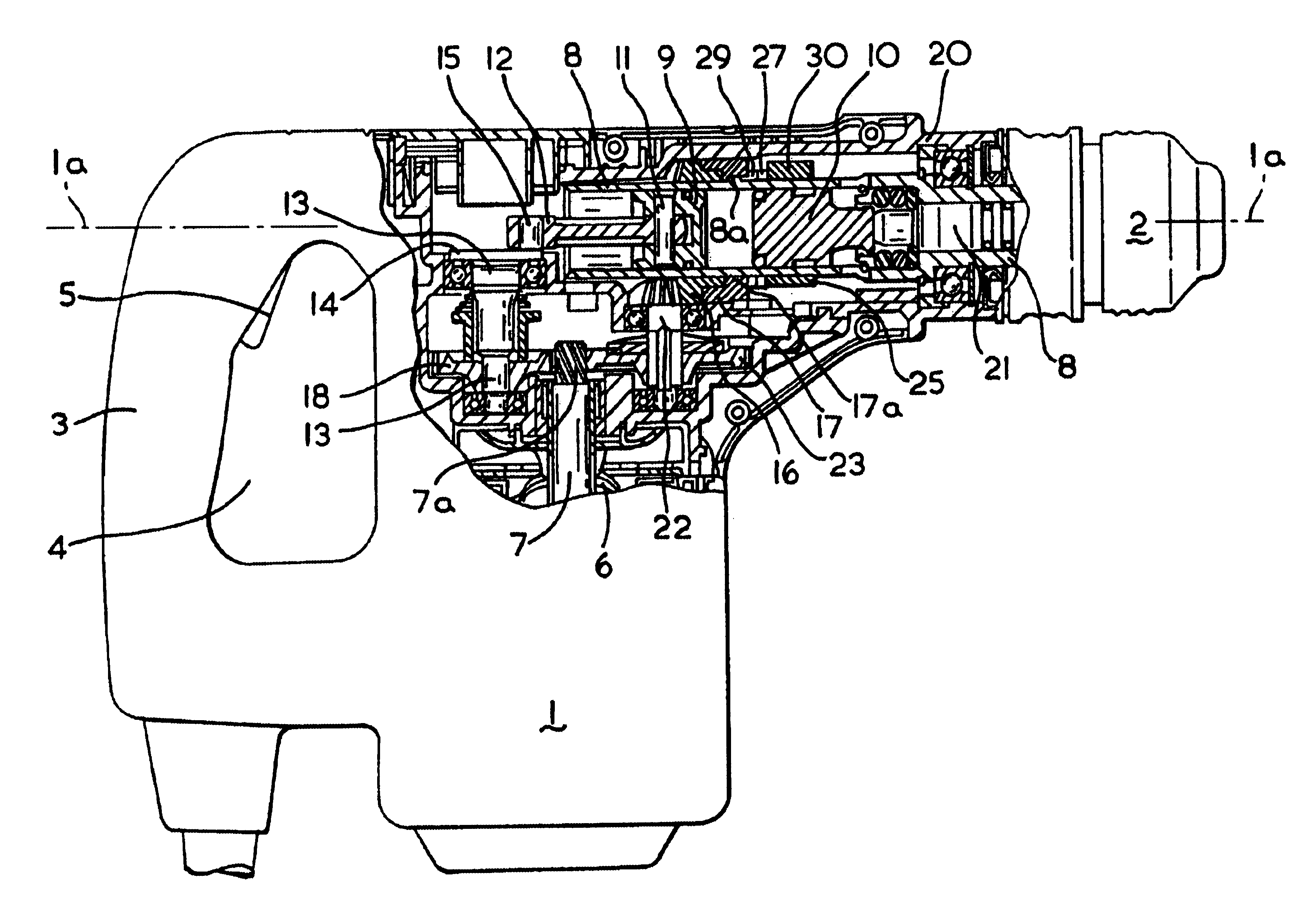
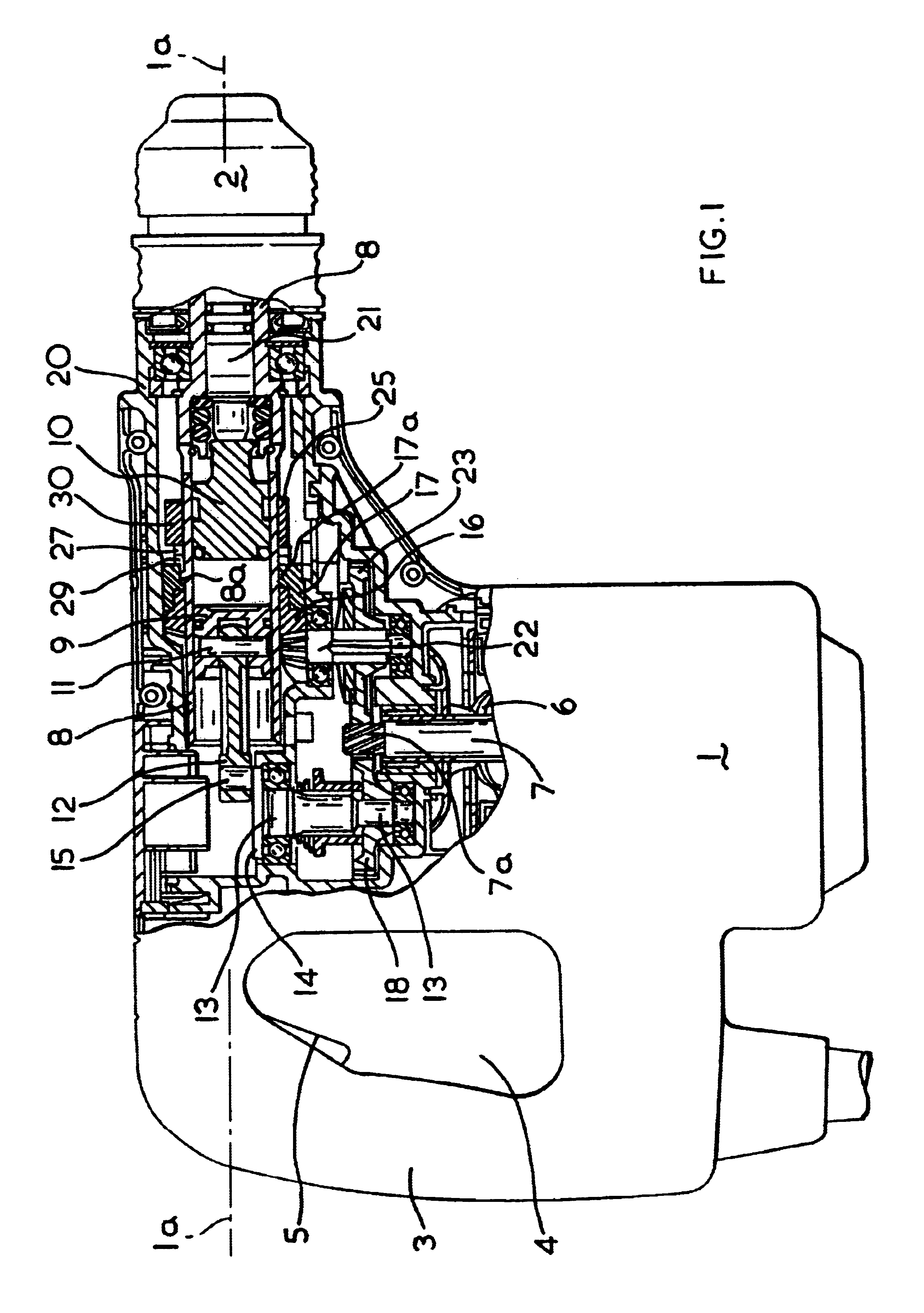
Referring to the accompanying drawings, the rotary hammer is comprised in the usual way of several components, including a hammer housing 1 having a working axis 1a. Housing 1 includes a gripping portion 3 at its rear end, so that a switch actuator 5 for switching an electric motor 6 on and off projects into a grip opening 4 which is defined at its rear side by the gripping portion 3. In the rear lower portion of the hammer housing 1, a mains lead, not shown, which serves to connect the rotary hammer to a power source, is led out.

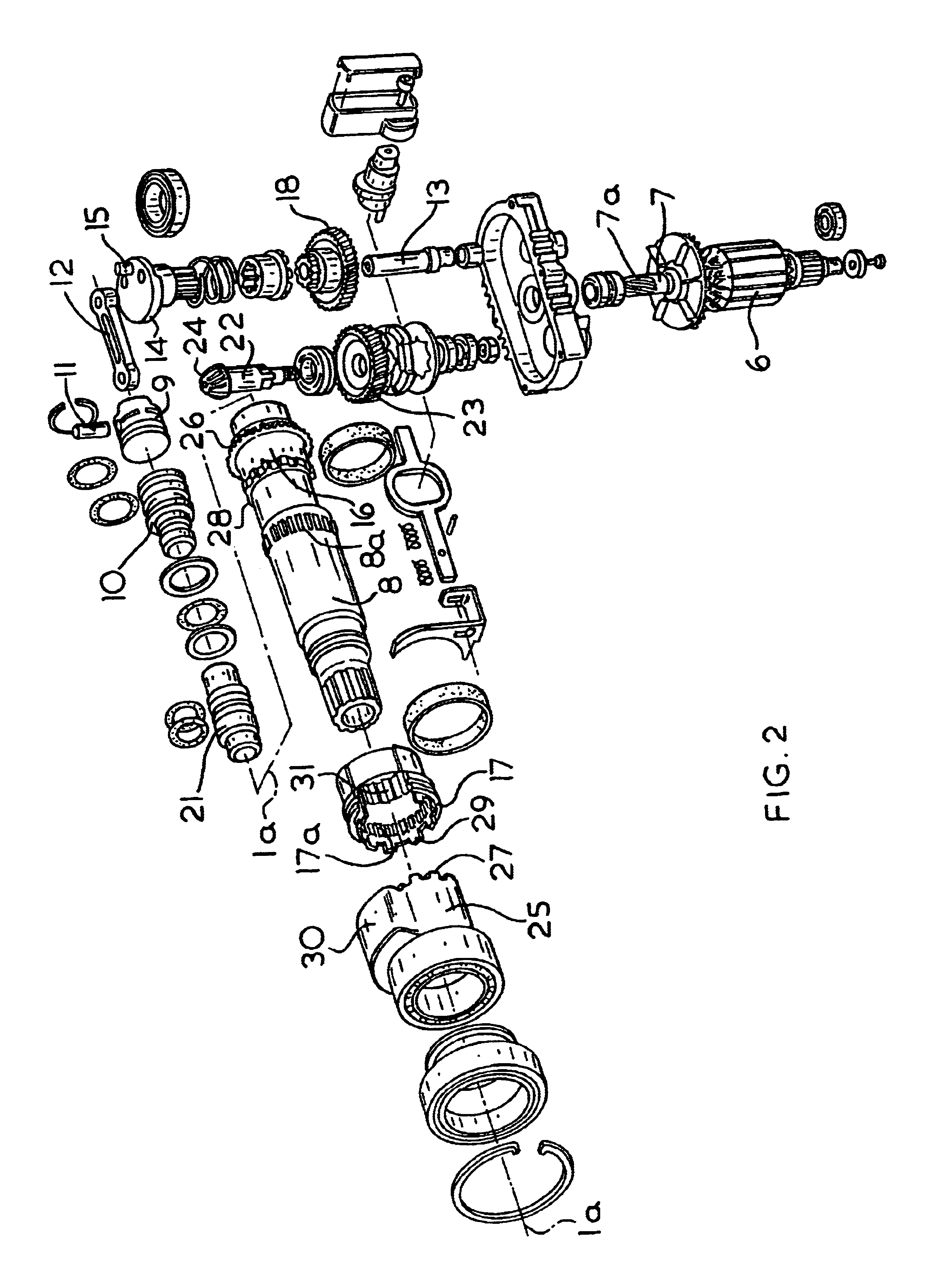
Located in the upper portion of the rotary hammer in FIG. 1 is an inner housing 20, preferably formed of half-shells and made from cast aluminium or the like, which extends forwards out of the rotary hammer housing 1 and in which a hammer spindle 8 is rotatably mounted. The rear end of the spindle 8 forms the guide tube or cylinder, provided in the known manner, for a pneumatic or air cushion hammer mechanism. A tool holder assembly 2 is mounted at the fron...


PUM

PropertyMeasurementUnit
eccentric massaaaaaaaaaa
structureaaaaaaaaaa
pressureaaaaaaaaaa

Abstract

A motor driven hammer comprising a tool holder and an air cushion hammering mechanism including a piston and a beat piece slideably located in a cylinder wherein reciprocation of the piston in the cylinder will cause the beat piece to hit a tool located in the tool holder, and further comprising an eccentric mass mounted for rotation about the axis of the cylinder and rotatingly driven by the motor via a gear arrangement so as to cause the bit mounted in the tool holder to be laterally diverted.

Description

BACKGROUND OF INVENTIONThis invention relates to motor driven hammers, and, in particular to hammers that incorporate an air cushion hammering mechanism.Such hammers will normally include a tool holder that can hold a hammer bit or chisel bit for acting on a workpiece, and an air cushion hammering mechanism which comprises a piston, a ram and a beat piece that are slidably located in a cylinder so that reciprocation of the piston in the cylinder will be transferred to the beatpiece via the ram and cause the beat piece to repeatedly hit a bit located in the tool holder. Some such hammers may have more than one mode. For example a hammer may be capable of being employed in a hammer only or so-called "chiselling" mode in which the piston reciprocates within the cylinder in order to cause the beat piece to hit the bit without any rotation of the tool, or alternatively a drilling only mode in which the cylinder may form part of a spindle connected to the tool holder and is caused to rota...

Claims


Application Information

Patent Timeline
Patent Type & Authority Patents(United States)
IPC IPC(8): B25D17/20B25D16/00B25D17/00
CPCB25D16/00B25D17/20B23B2265/12B25D2211/003B25D2211/068B25D2250/191
Inventor PLIETSCH, REINHARD
Owner BLACK & DECKER INC
Why Eureka
Try Eureka