Data recovery method and apparatus

Inactive Publication Date: 2004-05-25
EMC IP HLDG CO LLC
View PDF15 Cites 104 Cited by
  • Summary
  • Abstract
  • Description
  • Claims
  • Application Information

AI Technical Summary

Problems solved by technology

When data integrity is critical, such large scale disk memory facilities include some type of data redundancy.
As known, data on a standard device can, for a variety of reasons, become corrupt.
Oftentimes errors can occur while performing an update procedure like unrolling the redo logs thereby c

Method used


Image

  • Data recovery method and apparatus
  • Data recovery method and apparatus
  • Data recovery method and apparatus

Examples


Embodiment Construction

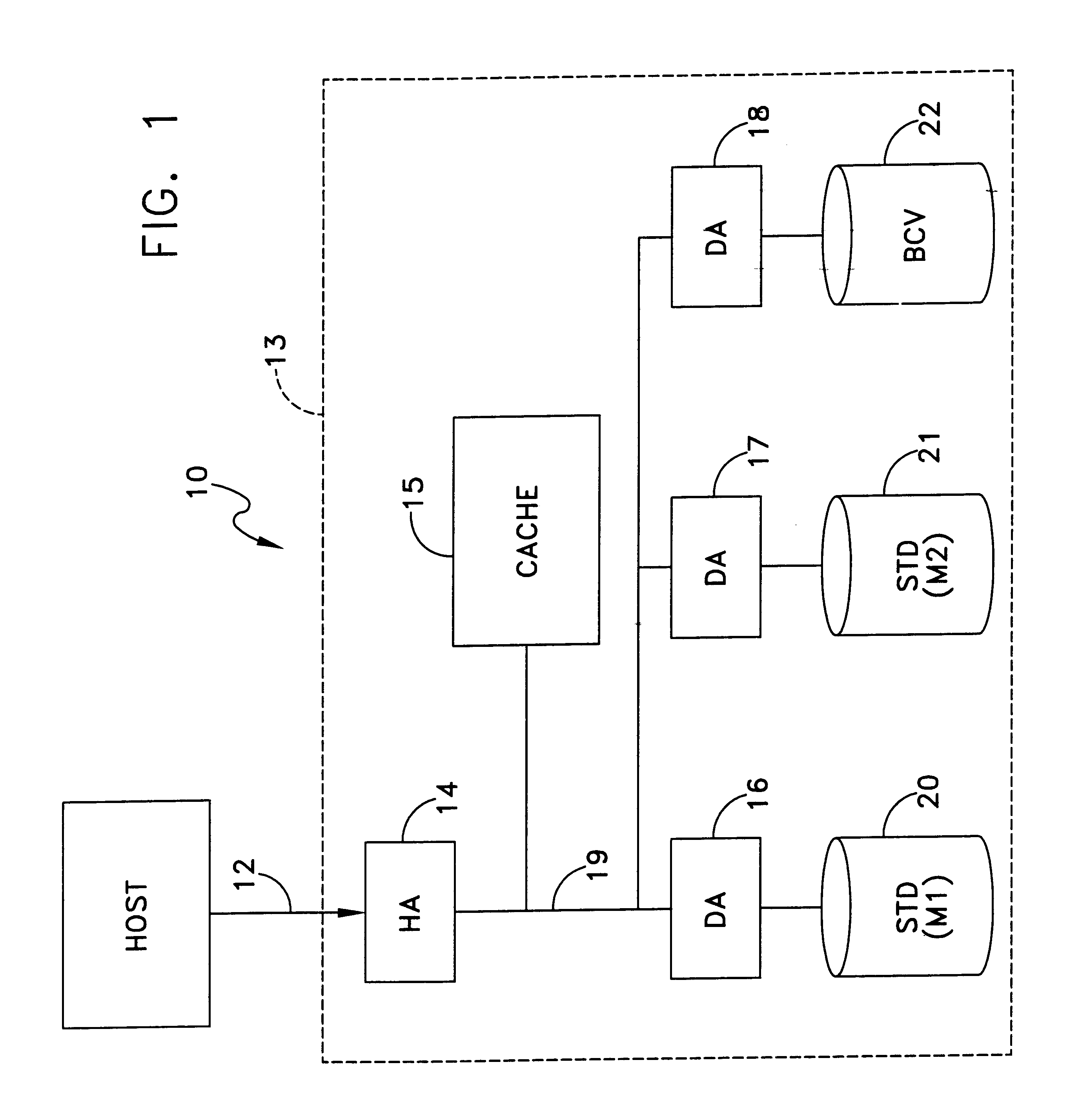
FIG. 1 depicts one example of a data processing system or network that can implement this invention. In this particular embodiment the configuration is that of a data processing system 10 with a host 11. Additional hosts can connect in parallel with the host 11 over a bus structure 12. A data storage facility 13 connects over the bus structure 12 to the 20 host 11. In this particular embodiment the data storage facility 13 is a local facility that includes a plurality of data stores. As will become apparent, this invention can be applied to other configurations in which certain data stores are located in a geographically remote location or in which individual data stores or portions of data stores are distributed throughout a local-area or wide-area network.

FIG. 1 defines this invention in terms of a Symmetrix data storage facility manufactured and sold by the assignee of this invention. In such a data storage facility 13, a host adapter (HA) 14, that includes a microprocessor contr...


PUM


Abstract

A method and apparatus for data recovery in a system involving a first data store acting as a standard device and a physical moving mirror data store that operates as moving mirror with a first mode to be synchronized and in a second, isolated mode. In response to a command to establish a third or protected restore operating mode, the data to be transferred in response to that command is identified. A restoration procedure copies data from the second data store to the first store to recover any data that may have been corrupted in the second data store. An update procedure acts on the restored data concurrently with the restoration procedure.

Description

1. Field of the InventionThis invention generally relates to the maintenance of data redundancy in a data storage facility and more particularly to recovering data in such a facility.2. Description of Related ArtMany data processing applications now operate on digital data processing systems that incorporate large scale memory facilities. These large scale memory facilities take many forms. One such form is a disk array storage device (DASD) in which data is stored at a local large scale disk memory with many physical disk drives. In other applications it may be desired to distribute the functions of equivalent devices over a network at different network nodes in a local-area or wide-area network.When data integrity is critical, such large scale disk memory facilities include some type of data redundancy. Memory mirrors provide on-site redundancy to protect against equipment failure. U.S. Pat. No. 5,206,939 to Yanai et al. and assigned to the same assignee as this invention disclose...

Claims


Application Information

Patent Timeline
IPC IPC(8): G06F11/00H02H3/05G06F11/14
CPCG06F11/1469G06F11/1471G06F11/1451G06F11/1456
Inventor GAGNE, MATHIEUKOPYLOVITZ, HAIMKEDEM, ISHAY
Owner EMC IP HLDG CO LLC
Why Eureka
Try Eureka