Heat storage tank

Inactive Publication Date: 2004-06-01
NIPPON SOKEN +1
View PDF9 Cites 22 Cited by
  • Summary
  • Abstract
  • Description
  • Claims
  • Application Information

AI Technical Summary

Benefits of technology

According to the present invention, in a heat storage tank, a first pipe member defining an introduction passage has a discharge port from which a fluid introduced through the introduction passage is injected into a tank body, a collision member is disposed in the tank body so that the fluid flowing from the discharge port collides with the collision member, a second pipe member defining a discharge passage has an introduction port from which the fluid in the tank body is introduced to be discharged outside the tank body through the discharge passage. The introduction port is positioned in the tank body at a side opposite to the discharge port with respect to the collision member. In addition, the collision member includes a shield portion disposed opposite to the discharge port to be separated from the discharge port by a predetermined dimension, and a guide portion, extending from the shield portion to a side of the discharge port, for guiding the fluid flowing along the shield portion toward a side of the discharge port. Accordingly, even when the flow speed of the fluid flowing from the discharge port is high, it can effectively prevent the fluid in the tank body from being mixed due to the fluid flowing from the discharge port. Thus, heat-storage performance of the fluid in the tank body can be improved.
Preferably, a mixture protection plate, for preventing the fluid in the tank body from being mixed due to the fluid flowing from the discharge port, is provided to have a plurality of through holes through which the fluid flowing from the discharge port flows. In addition, the mixture protection plate is disposed between the collision member and an inner surface of the tank body. Therefore, the fluid from the discharge port passes through the through holes of the mixture protection plate after colliding with the shield portion and after being guided by the guide portion. Accordingly, it can further effectively prevent the fluid in the tank body from being mixed due to the injection fluid from the discharge port.
On the other hand, according to the present invention, a plate-like shield portion is disposed in the tank body, instead of the collision member. In this case, the shield portion includes a collision wall surface with which the fluid flowing out from the discharge port collides, and a guide wall surface extending from the collision wall surface for guiding the fluid after colliding with the collision wall surface. The collision wall surface is disposed to face the discharge port and to be separated from the discharge port by a predetermined distance, and the guide wall surface is provided such that the fluid after colliding with the collision wall surface is prevented from directly flowing toward the introduction port. In addition, the introduction port and the discharge port are positioned at both opposite sides relative to the shield portion, and the collision wall surface and the guide wall surface of the shield portion have a moment center (G) that is located at a position separated from the discharge passage. Accordingly, it can effectively prevent the fluid in the tank body from being mixed due to the fluid injection from the discharge port.
Preferably, the moment center (G) is located at a position offset to a side of the discharge passage relative to the introduction passage. Therefore, the fluid after colliding with the collision wall surface can be effectively guided by the guide wall surface.

Problems solved by technology

However, in this heat storage tank, the following problems have been found by detail studies performed by the present inventors.

Method used


Image

  • Heat storage tank
  • Heat storage tank
  • Heat storage tank

Examples


first embodiment

(First Embodiment)

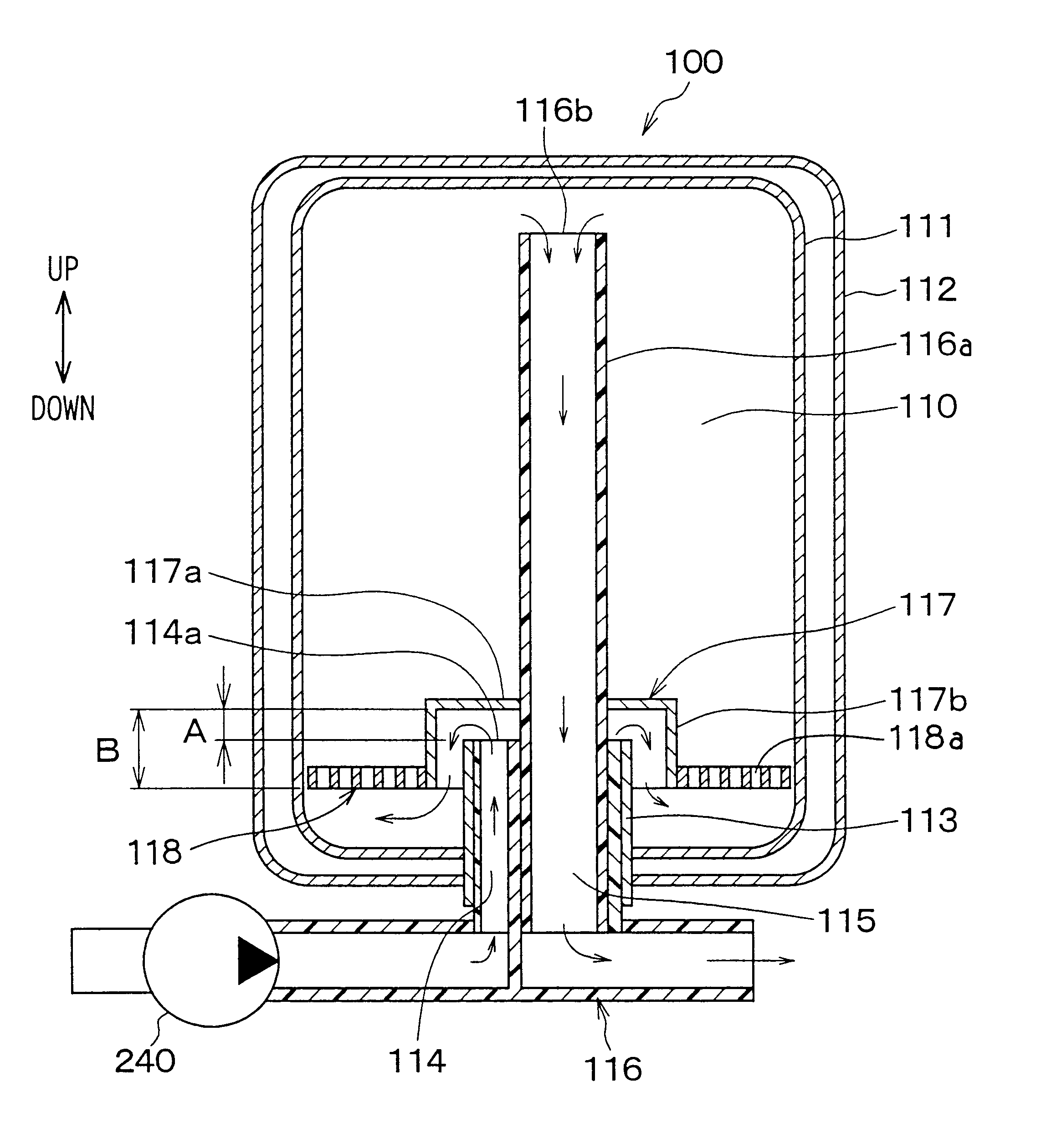
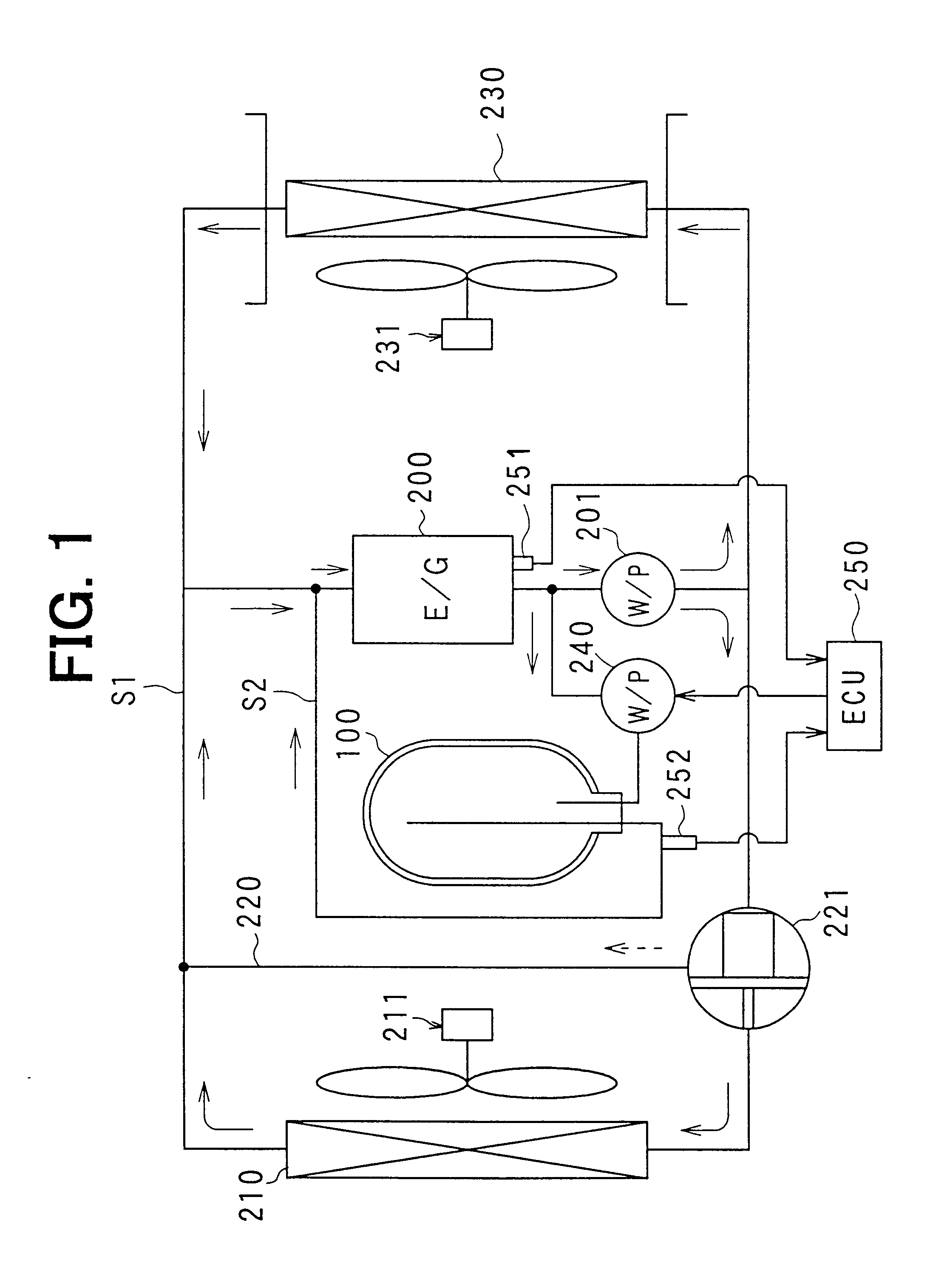
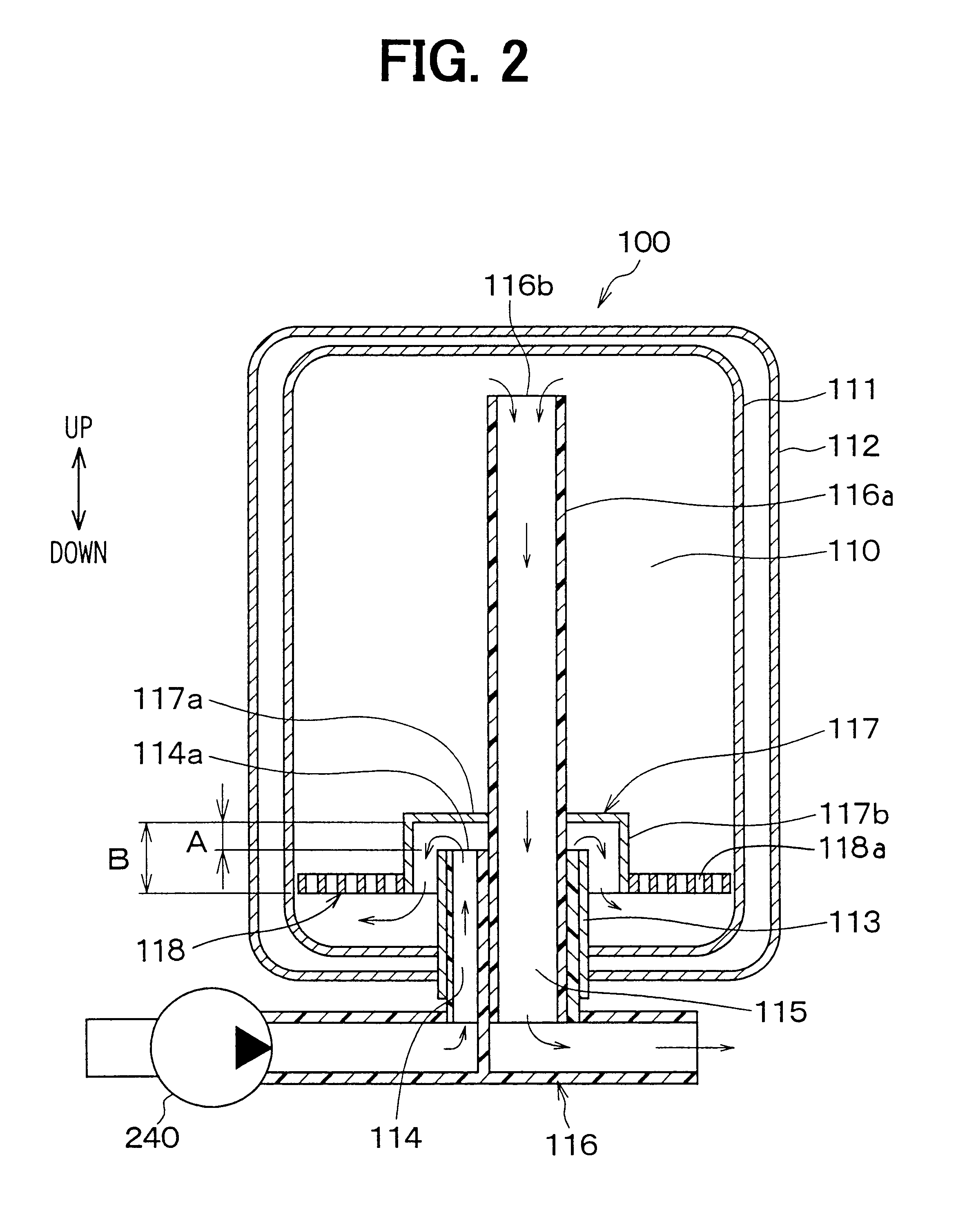
In the first embodiment, as shown in FIG. 1, a heat storage tank 100 according to the present invention is typically used for a heat storage tank in a vehicle water circuit. A radiator 210 provided in the water circuit is a heat exchanger which cools water by performing heat-exchange between the water from a water-cooled engine (E / G) 200 and air. The water flows through the engine 200 and cools the engine 200. A bypass circuit 220 is a water circuit through which water circulates while bypassing the radiator 210. A thermostat 221 adjusts an amount of water flowing into the bypass circuit 220 and an amount of water flowing into the radiator 210 so as to set the temperature of the engine 200 at a predetermined temperature. A blower 211 blows cooling air (i.e., outside air) to the radiator 210, and a heater core 230 is disposed to heat air blown into a passenger compartment using the engine-cooling water (hot water) as a heating source. A blower 231 is an interior blo...

second embodiment

(Second Embodiment)

In the second embodiment, as shown in FIGS. 5A, 5B, the mixture protection plate 118 is provided at the peripheral side end of the shield portion 117a in the collision member 117. The shield portion 117a and the mixture protection plate 118 are integrally formed by pressing a plate material, and the guide cover 117b having an approximate cylindrical shape is bonded to this integrally formed member by a bonding means such as welding and brazing. Even in this case, the advantage described in the first embodiment can be obtained.

third embodiment

(Third Embodiment)

In the third embodiment, as shown in FIGS. 6A, 6B, a wall surface of the collision member 117 including the shield portion 117a and the guide cover 117b is formed into a dome shape having a curvature center at the side of the discharge port 114a. The wall surface of the collision member 117 may have another shape such as a spindle shape without being limited to a spherical shape. Even in the third embodiment, the advantage described in the first embodiment can be obtained.


PUM


Abstract

In a heat storage tank, a discharge port of an introduction passage is covered by a cup-shaped collision member constructed by a shield portion and a guide cover. In addition, a mixture protection plate having plural through holes is disposed in a tank body between the collision member and an inner surface of the tank body. Therefore, a high-speed water stream, upwardly injected from the discharge port, collides with the shield portion, and turns its flow direction by an approximately right angle. Thereafter, the water stream is guided by the guide cover to a lower side of the mixture protection plate. Accordingly, it can prevent water stored in the tank body from being mixed even when the injection water stream has a high speed.

Description

This application is related to and claims priority from Japanese Patent Applications No. 2001-203660 filed on Jul. 4, 2001, and No. 2001-346242 filed on Nov. 12, 2001, the contents of which are hereby incorporated by reference.1. Field of the InventionThe present invention relates to a heat storage tank in which a fluid is thermally insulated and stored, and is suitably applied to a vehicle heat storage tank in which cooling water (hot water) for cooling a vehicle engine is thermally insulated and stored.2. Description of Related ArtFor example, in a heat storage tank disclosed in JP-A-10-71840, a mixture protection plate having plural holes is provided around a water inlet, so that it can restrict engine-cooling water (hot water) in a tank body from being forcibly agitated and mixed due to an injection water from the water inlet.However, in this heat storage tank, the following problems have been found by detail studies performed by the present inventors. Here, opening areas of the...

Claims


Application Information

Patent Timeline
Patent Type & Authority Patents(United States)
IPC IPC(8): B60H1/00F28D20/00F01P3/20B60H1/08F02G5/00F24F5/00
CPCB60H1/00492F28D20/0039F28D2020/0069F28D2020/0086Y02E60/142B60H1/00499Y02E60/14
Inventor ONIMARU, SADAHISAMORIKAWA, TOSHIOBAN, KOICHITOYOSHIMA, TAKASHI
Owner NIPPON SOKEN
Why Eureka
Try Eureka