

Beam scanning printer
a beam scanning and printer technology, applied in the direction of digital output to print units, instruments, inking apparatus, etc., can solve the problems of large space, difficult control of optical axes, and high cost of solutions
- Summary
- Abstract
- Description
- Claims
- Application Information
AI Technical Summary
Benefits of technology
Problems solved by technology
Method used
Image

Examples
first embodiment
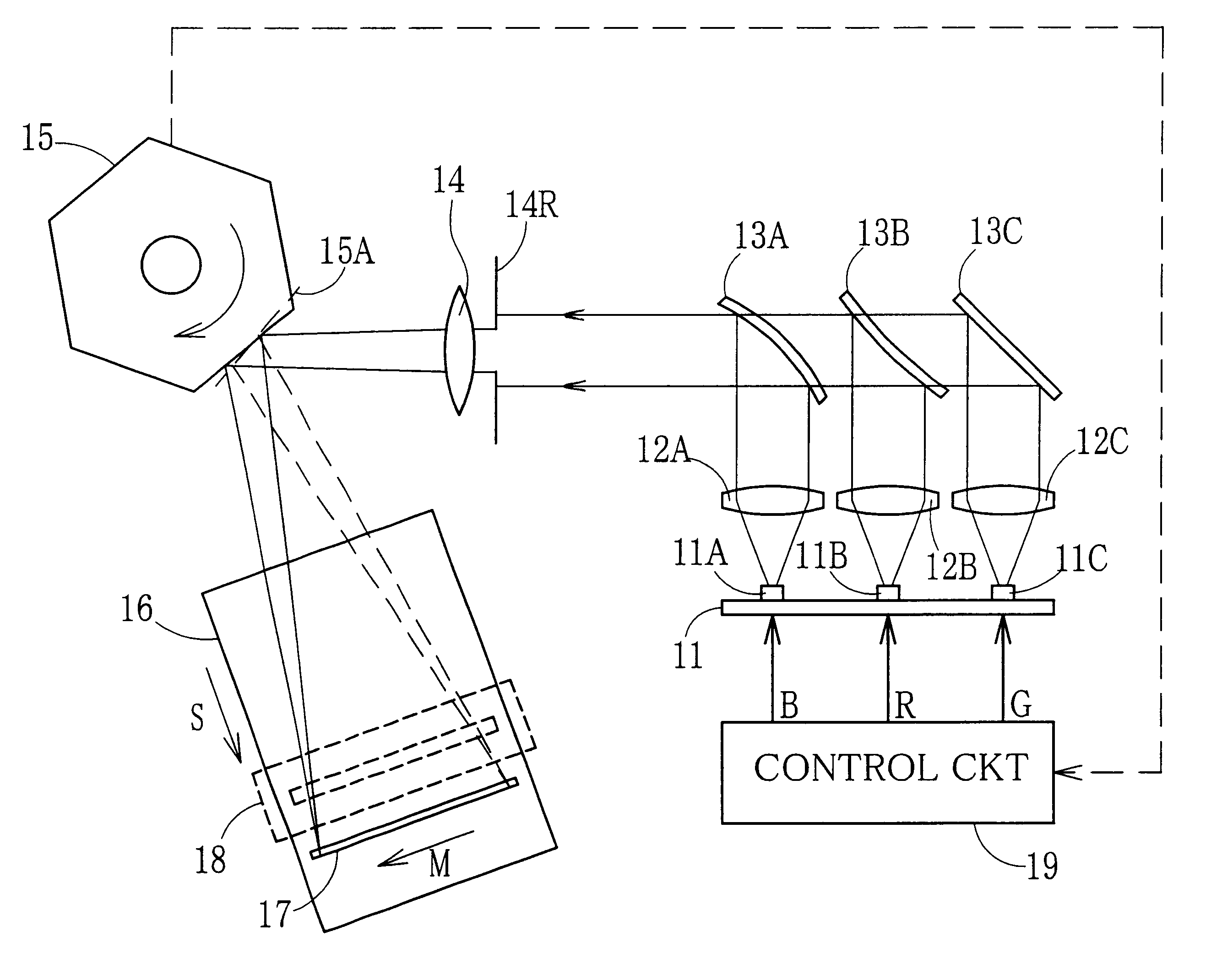
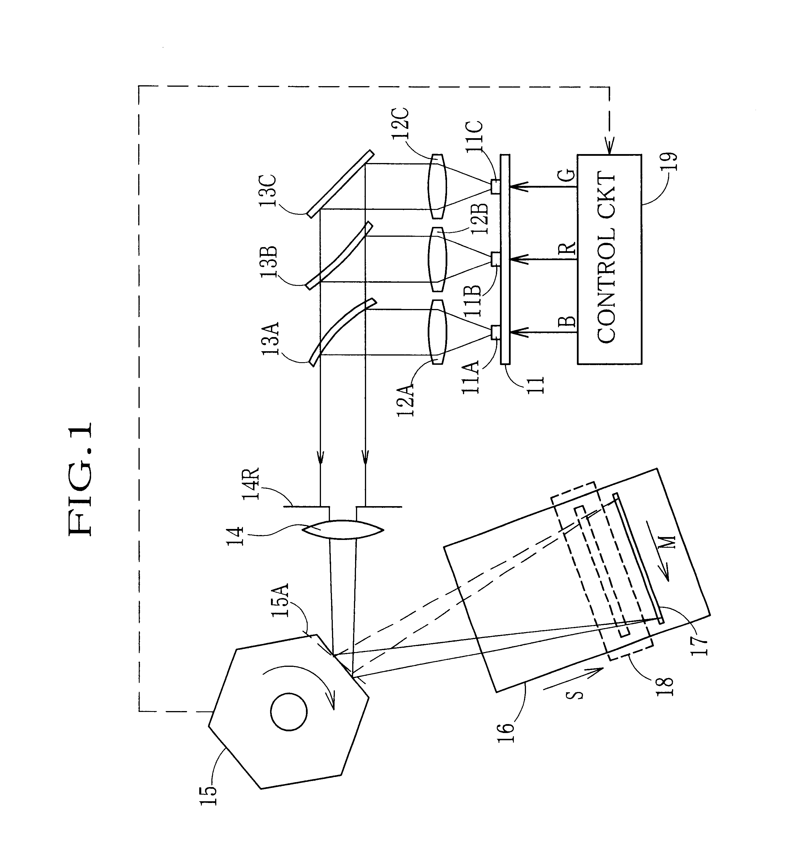
According to the beam scanning printer of the first embodiment, superior properties of the LED are utilized fully for recording an electronic image onto a photographic sheet. More specifically, with a simple current control circuit, the output has a wide dynamic range, follows the input at a high speed, can be controlled in a flexible and infinite number of level grades, and gains a high fidelity to the input. Accordingly, the beam scanning printer can produce a photo-print that is rich in coloration and high in color reproduction.
Although the current values for driving the LEDs 11A, 11B and 11C are controlled to modulate the light intensities in accordance with the three color densities of each pixel in the above embodiment, it is possible to control driving cycle or time per pixel of the individual LED 11A, 11B or 11C in accordance with the three color densities of each pixel. It is also possible to control exposure amount to each color beam by controlling intensity, driving cycle...
second embodiment
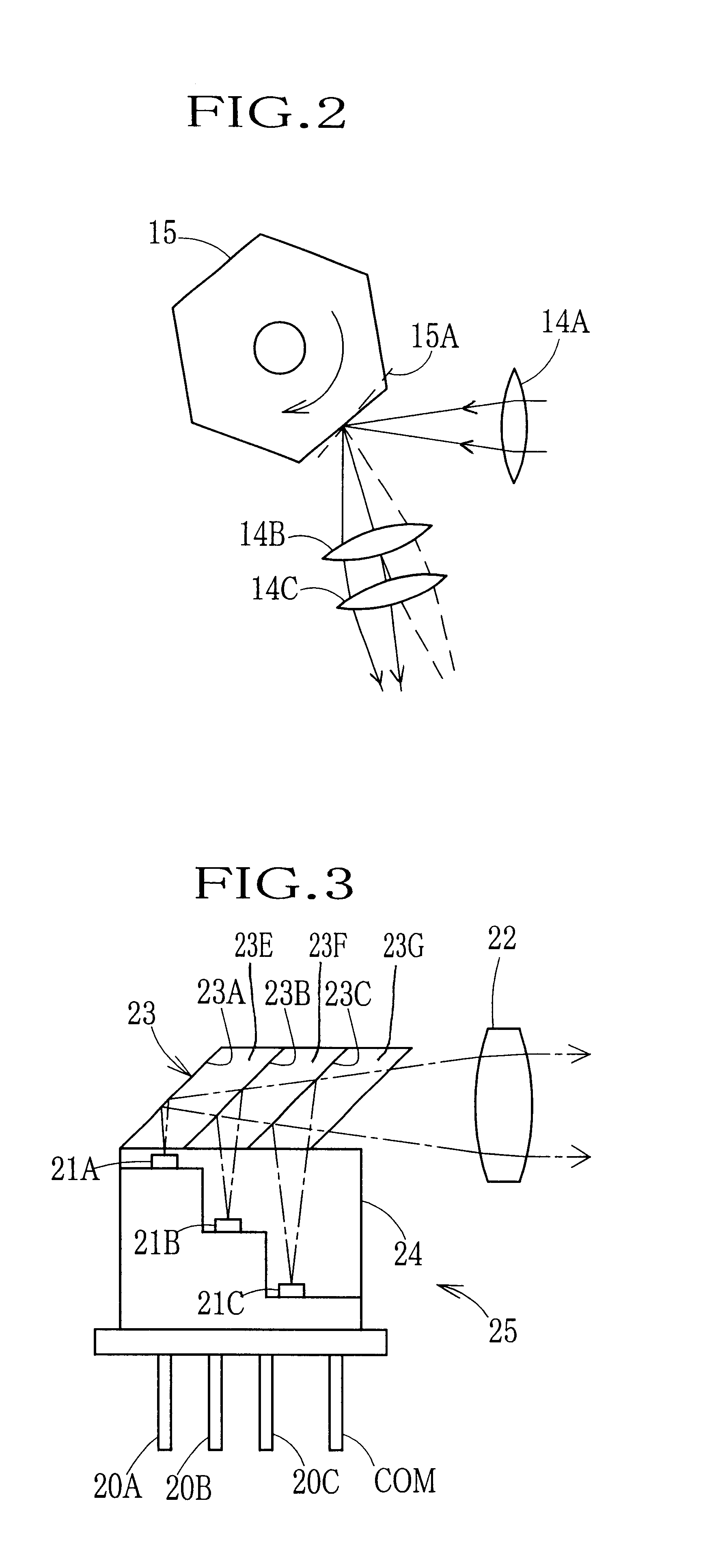
the total and selective reflection surfaces 23A to 23C and the LEDs 21A to 21C are integrated into a unit wherein these elements are correctly positioned. Therefore, it is easy to design and assemble the optical system in comparison with the case where the optical system is constituted of separate members.
Since the optical axes of the radiating beams from the LEDs 21A to 21C are aligned, and then the coaxial radiating rays are converted into parallel rays through the single collimator lens 22, the number of lenses necessary for constituting the beam scanning printer is reduced as compared to a case where there are individual collimator lenses for the respective LEDs 21A to 21C. Thus, the whole size of the optical system is reduced.
In the second embodiment, the respective optical path lengths from the LEDs 21A to 21C to the collimator lens 22 via the reflector section 23 are made equal to each other by adjusting physical distances from the mounting surfaces for the LEDs 21A to 21C of...
third embodiment
FIG. 5 shows a light source section of a third embodiment that consists of a light source unit 38 and a cone-shaped light converging member 37, and virtually outputs a spot light of the three color.
On a base plate 36 of the light source unit 38, three LEDs 31A, 31B and 31C for blue, red and green are arranged in a line at a distance of 100 .mu.m from each other. The LED 31A emits green rays when the current is applied between the a terminal 30A and a common terminal COM, the LED 31B emits red rays when the current is applied between a terminal 30B and the common terminal COM, and the LED 30C emits blue rays when the current is applied between a terminal 30C and the common terminal COM. By controlling the current value applied to the individual LED 31A, 31B or 31C, the light intensity of each color and thus the color balance between the three colors may be changed appropriately.
The cone-shaped light converging member 37 is connected to an exit surface of the light source unit 38. The...
PUM
 Abstract
Description
Claims
Application Information