Chemical supply system

a chemical supply and pump technology, applied in the direction of engine diaphragms, diaphragm valves, instruments, etc., can solve the problems of increasing and reducing the cleaning speed of the substrate cleaning apparatus

Inactive Publication Date: 2004-07-20
ULTRACLEAN TECH RES INST
View PDF14 Cites 62 Cited by
  • Summary
  • Abstract
  • Description
  • Claims
  • Application Information

AI Technical Summary

Problems solved by technology

Accordingly, the whole system becomes a very large scale and complex inevitably in this case.
Further, generation of particles and (metal) contamination from various liquid-contact portion caused by complication of the substra

Method used


Image

  • Chemical supply system
  • Chemical supply system
  • Chemical supply system

Examples


second example

Successively, the second example of the present invention will be described. In this example, like the first example, a substrate cleaning apparatus of single wafer spin cleaning type comprising a cleaning chamber and a chemical supply system, is disclosed, but it differs on the point that the construction of the chemical supply apparatus of the chemical supply system is different. The same components or the like as those of the substrate cleaning apparatus of the first example are denoted by the same references, and their explanations will be omitted.

FIG. 35 is a schematic sectional view showing the whole construction of the substrate cleaning apparatus of this example.

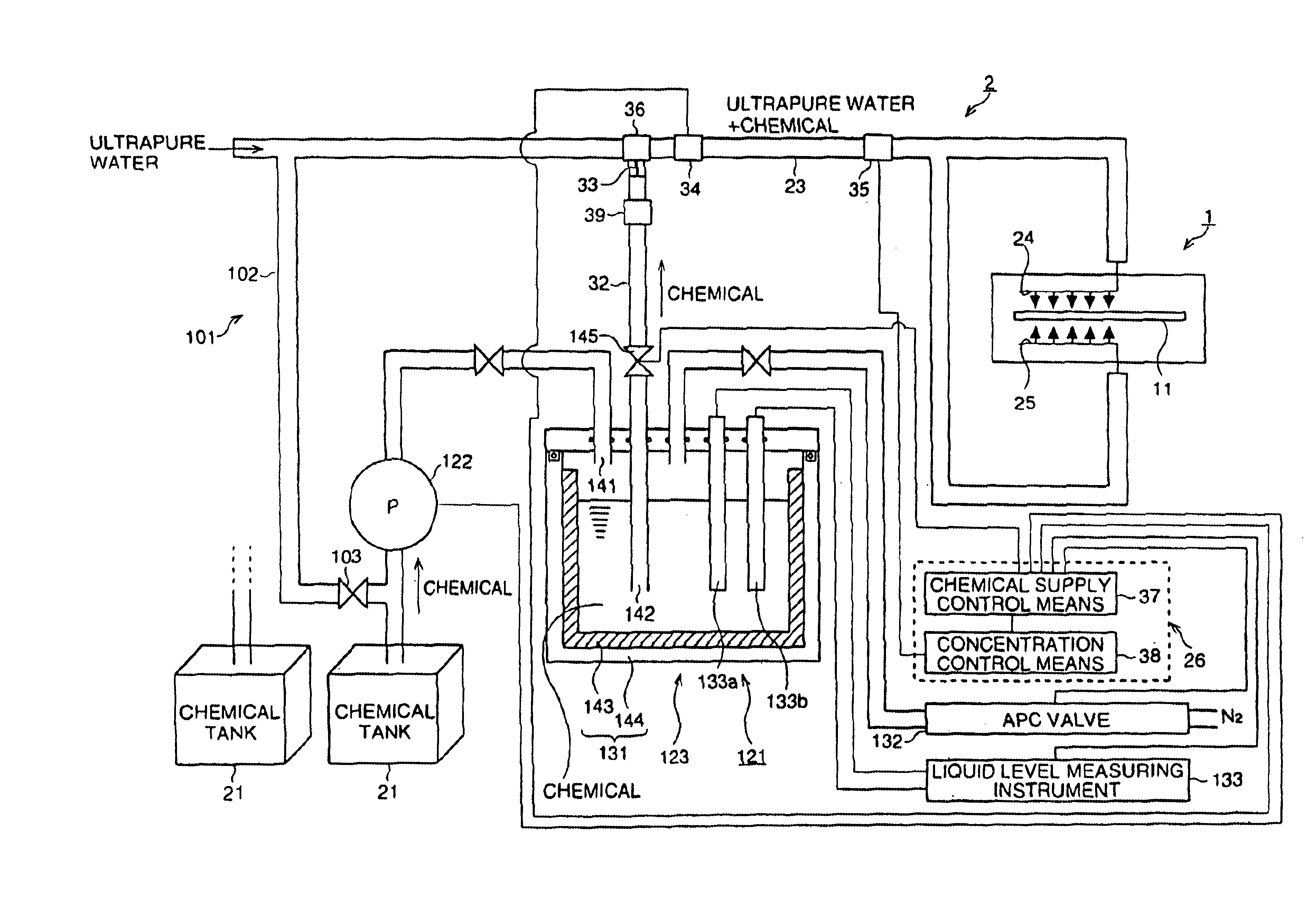
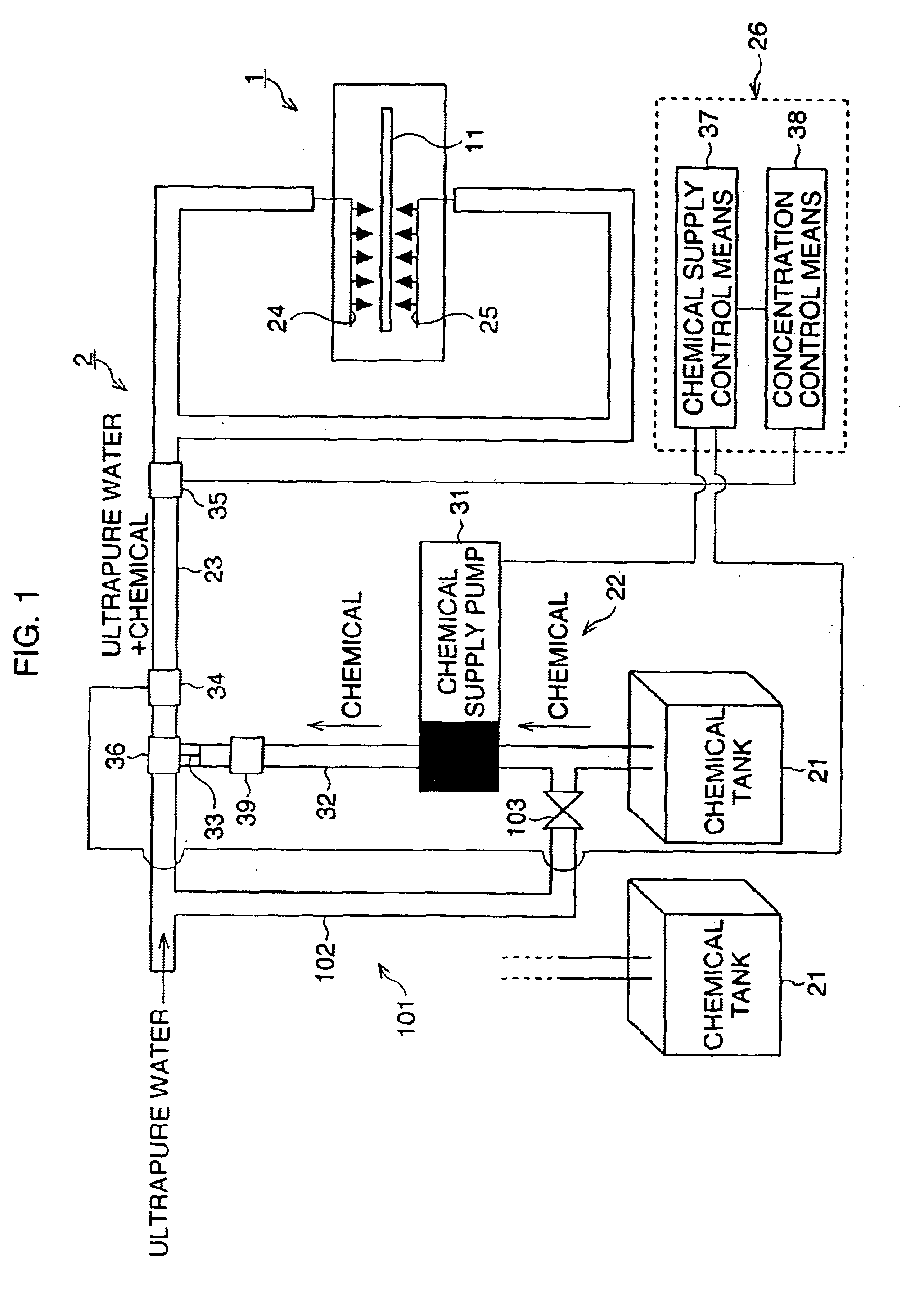
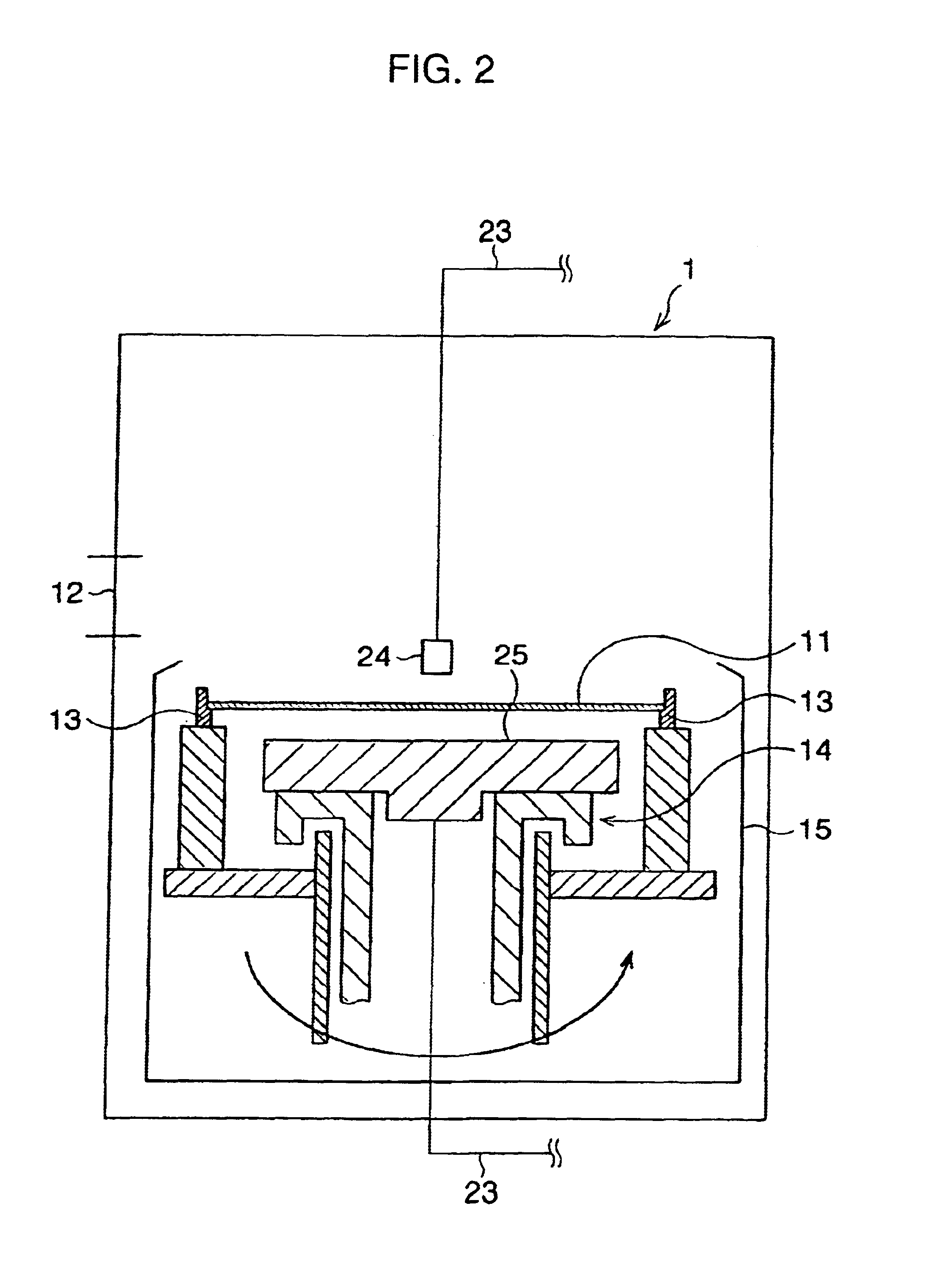
The substrate cleaning apparatus of this example is constructed by comprising a cleaning chamber 1 and a chemical supply system 2. Here, the chemical supply system 2 is constructed by comprising a chemical storage tank 21, a chemical supply apparatus 121 connected to the chemical storage tank 21 for positively perfor...


PUM


Abstract

A chemical supply system comprises, as principal elements, a chemical storage tank in which a liquid chemical for cleaning is stored in the state of its formulated concentrate, a chemical supply apparatus connected to the chemical storage tank for positively performing chemical supply, a piping system connected to the chemical supply apparatus to form a supply flow passage that is a passage for ultrapure water which the liquid chemical is to be mixed with, a pair of discharge nozzles disposed at end portions of the piping system so as to oppose surfaces of a wafer set in a cleaning chamber to supply a cleaning liquid onto the surfaces. Thereby, remarkable miniaturization/simplification of a cleaning liquid supply system including chemical tanks is intended, it is made possible easily and rapidly to compound and supply a cleaning liquid at an accurate chemical concentration, and particles or the like being generated and mixing in a cleaning liquid, are suppressed to the extremity.

Description

1. Field of the InventionThe present invention relates to a chemical supply pump, a chemical supply apparatus, and a chemical supply system (a chemical supply method) for accurately supplying a desired quantity of a liquid chemical, in particular, it is suitable for applying to a substrate cleaning apparatus (a substrate cleaning method) for cleaning semiconductor wafers or the like.2. Description of the Related ArtConventionally in a semiconductor wet process, used is a substrate cleaning apparatus for performing a process such as cleaning with a cleaning liquid of ultrapure water and a liquid chemical. As such a substrate cleaning apparatus, remarked is a substrate single wafer spin cleaning apparatus in which substrates are loaded one by one and a cleaning liquid is supplied with rotating the substrate in a circumferential direction.In a conventional substrate cleaning apparatus, it was indispensable to provide a plurality of large-sized cleaning liquid storage tanks for preparin...

Claims


Application Information

Patent Timeline
IPC IPC(8): B01F15/04B01F15/02B01F5/04F04F7/00F04B43/02F04B43/04F04B43/00F16K7/12G05D11/00G05D11/13H01L21/304B01F25/60B01J4/02F04B13/02
CPCB01F5/0471B01F5/0475B01F15/0203B01F15/024B01F15/0244B01F15/042F04B43/0054F04B43/02F04B43/046F04F7/00F16K7/123G05D11/138B01F2215/0096H01L21/67051B01F25/3142B01F25/314B01F35/712B01F35/71755B01F35/71761B01F35/8311B01F2101/58
Inventor NITTA, TAKAHISAMIKI, NOBUHIROYAMAGUCHI, YOSHIAKI
Owner ULTRACLEAN TECH RES INST
Why Eureka
Try Eureka