Two-wire controlling and monitoring system for irrigation of localized areas of soil

Inactive Publication Date: 2004-07-20
S RAIN CONTROL
View PDF8 Cites 142 Cited by
  • Summary
  • Abstract
  • Description
  • Claims
  • Application Information

AI Technical Summary

Problems solved by technology

Sinusoidal signals being AC signals generally need to be converted into DC in order to drive microprocessor electronic circuitry adding

Method used


Image

  • Two-wire controlling and monitoring system for irrigation of localized areas of soil
  • Two-wire controlling and monitoring system for irrigation of localized areas of soil
  • Two-wire controlling and monitoring system for irrigation of localized areas of soil

Examples


first embodiment

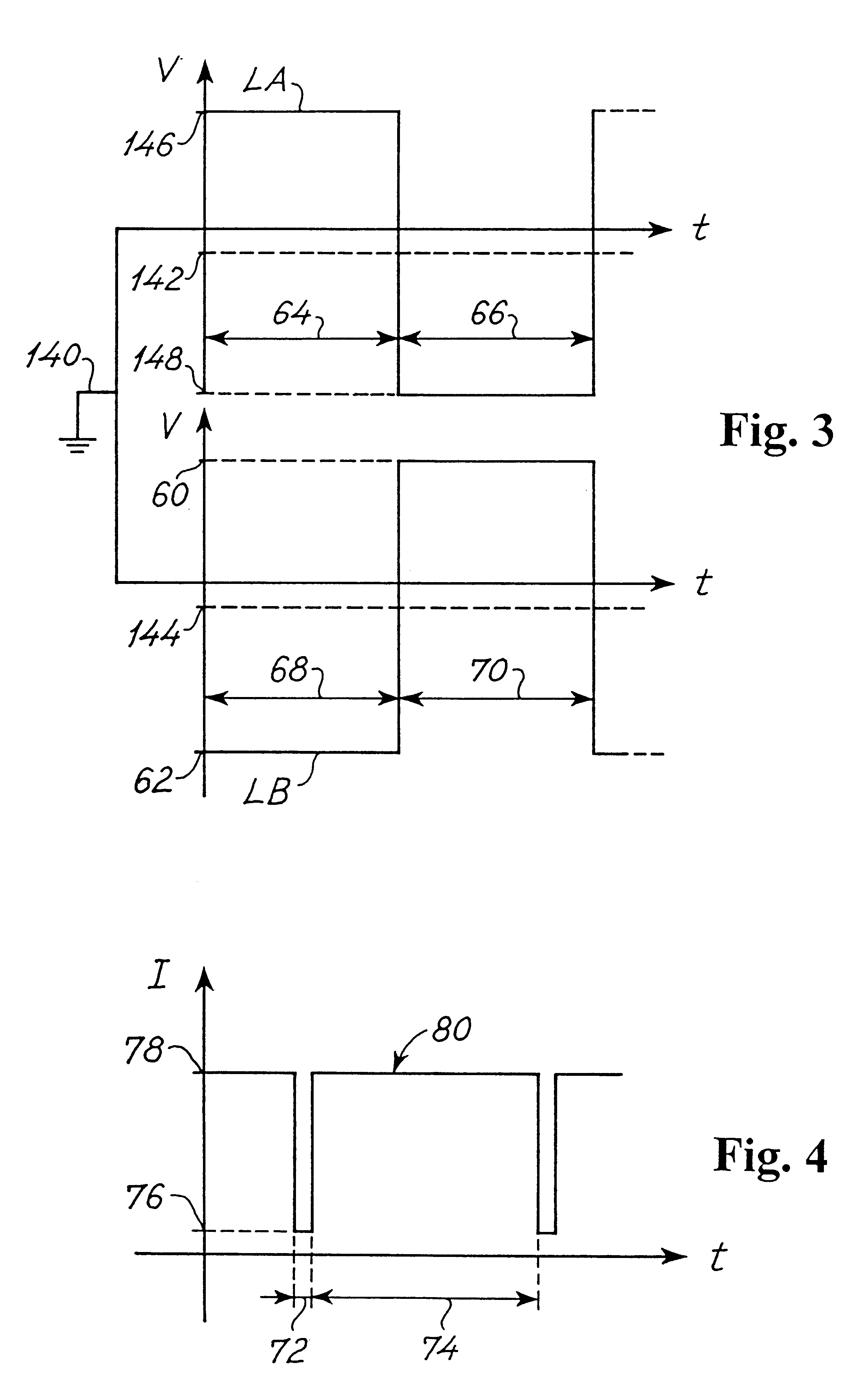
In order to reduce power consumption of the controllable irrigation valves 42 the control signal 100 in the presently preferred embodiment of the invention is construed from a series of square wave pulses 114 constituting an pulsed inrush signal 110 and constituting a pulsed hold signal 112. The square wave pulse 114 defines a voltage maximum 92 having a pulse width 94 and defines a voltage minimum 90 having a pulse width 96 in the pulsed inrush signal 110 and defines the voltage maximum 92 having a pulse width 99 and defines the voltage minimum 90 having a pulse width 98 in the pulsed hold signal 112. According to the present invention the pulse width 94 and the pulse width 96 and the pulse width 99 are 1 ms, but may be any value in the range 100 .mu.s to 0.1 s. The pulse width 98 is 10 ms, but may be any value in the range 6 ms to 30 ms. The average voltage of the pulsed inrush signal 110 is equal to the maximum voltage 82 of the inrush signal 102 and the average voltage of the pu...

example

The sensor decoder 52 shown in FIG. 11 and as described above was implemented in a prototype version from the following components.

The line decoder 44 shown in FIG. 12 and as described above was implemented in a prototype version from the following components.

The line decoder 44 shown in FIG. 12 and as described above was implemented in a prototype version from the following components.

The microprocessor and storage section shown in FIGS. 14a and 14b and as described above was implemented in a prototype version from the following components.

The power output stage shown in FIGS. 15a and 15b and as described above was implemented in a prototype version from the following components.

The mark sender shown in FIGS. 16a and 16b and as described above was implemented in a prototype version from the following components.


PUM


Abstract

A two-wire controlling and monitoring system for in particular irrigation of localized areas of soil according to a aspect of the invention comprises a water pipeline, a first plurality of controllable irrigation valves, a second plurality of field sensors measuring specific irrigation parameters, and a third plurality of localized irrigation control units. The third plurality of localized irrigation control units each comprises a sensor decoder connected to a specific field sensor of the second plurality of field sensors and/or a line decoder connected to a specific controllable irrigation valve of the first plurality of controllable irrigation valves. The two-wire controlling and monitoring system further comprises a controller and power supply unit having a set of schedules of instructions and supplying power by applying a first alternating DC voltage signal to a two-wire cable interconnecting the controller and power supply unit and the third plurality of localized irrigation control units. The two-wire cable provides the power from the controller and power supply unit to each of the third plurality of localized irrigation control units. The controller and power supply unit transmits the schedules of instructions to the third plurality of localized irrigation control units through the two-wire cable and receives the specific irrigation parameters from the third plurality of localized irrigation control units through the two-wire cable.

Description

This particular invention relates generally to a two-wire controlling and monitoring system particularly for irrigation of localized areas of soil.DESCRIPTION OF THE RELATED ARTThe most commonly known two-wire irrigation control systems, such as control systems disclosed in U.S. Pat. Nos. 4,007,458 and 4,176,395 hereby incorporated by reference, provide control of a number of remotely located irrigation or sprinkler valves from a central location by means of control signals encoded on to a single pair of power transmission lines linking a central encoder and a number of remote decoders.The two-wire irrigation control system according to U.S. Pat. No. 4,007,458 encodes and transmits an address of a specific remotely located irrigation valve and on / off signals onto an alternating current signal (AC) by clipping half portions of the signal to represent zero values.Similarly the two-wire interactive irrigation control system according to U.S. Pat. No. 4,176,395 transmits data by selecti...

Claims


Application Information

Patent Timeline
IPC IPC(8): A01G25/16
CPCA01G25/16A01G25/167Y10T137/86389Y10T137/1866
Inventor CHRISTIANSEN, TOM N.O SLASHED.HR
Owner S RAIN CONTROL
Why Eureka
Try Eureka