Electrostatic chuck and processing apparatus for insulative substrate

Inactive Publication Date: 2004-07-27
ULVAC INC +1
View PDF9 Cites 62 Cited by
  • Summary
  • Abstract
  • Description
  • Claims
  • Application Information

AI Technical Summary

Problems solved by technology

Therefore, conventionally, it is impossible to apply a fixing method using an electrostatic chuck in the manufacturing apparatus for forming devices on these wafers.
However, since the electrostatic chuck of the conventional art can attract only

Method used


Image

  • Electrostatic chuck and processing apparatus for insulative substrate
  • Electrostatic chuck and processing apparatus for insulative substrate
  • Electrostatic chuck and processing apparatus for insulative substrate

Examples


Embodiment Construction

)

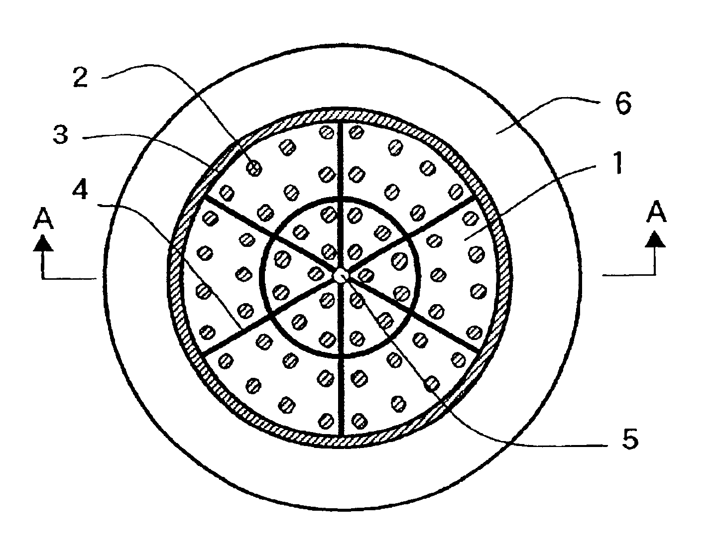
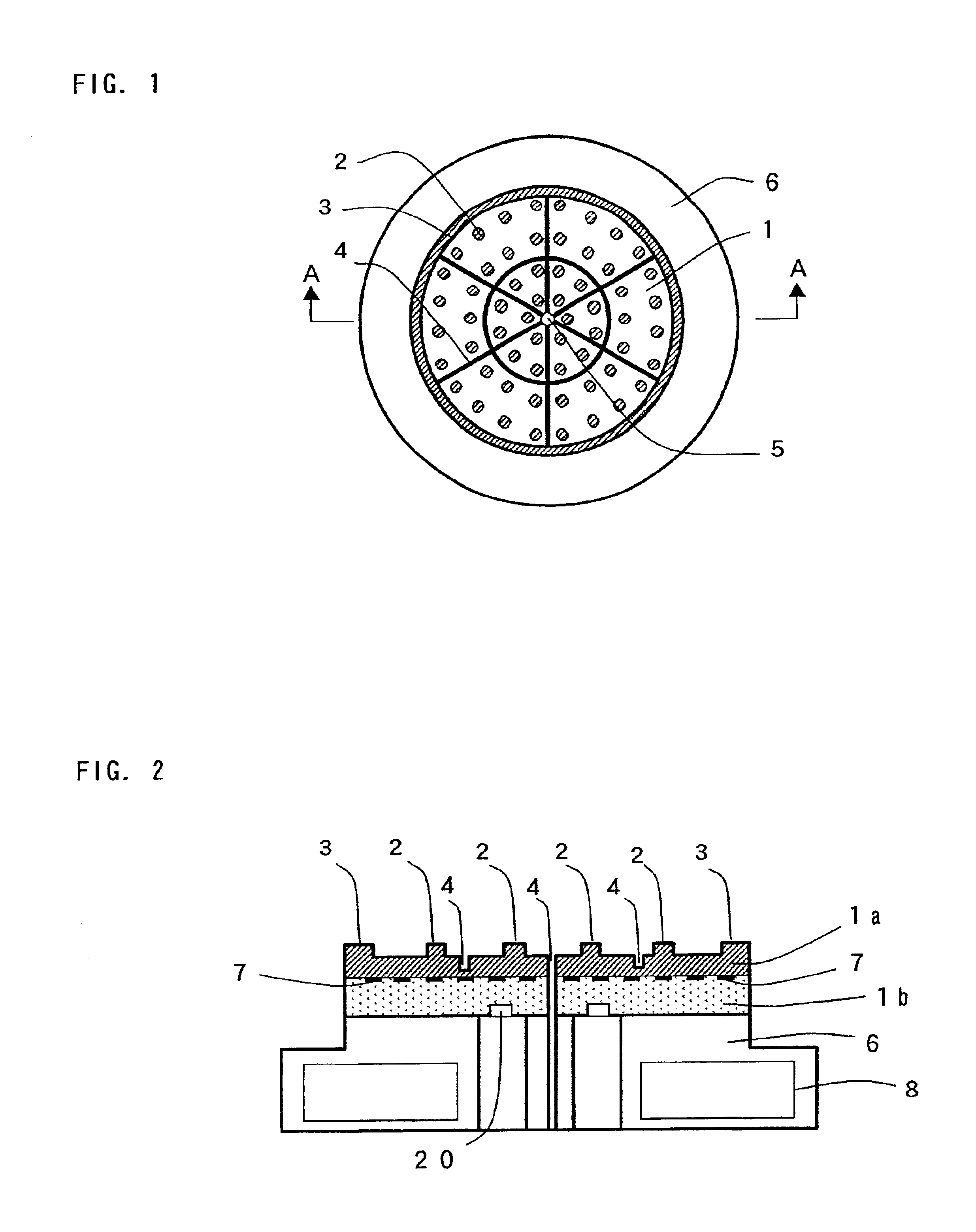
Hereinafter, embodiments according to the present invention will be fully explained with reference to the attached drawings. FIG. 1 is a plan view showing an embodiment of an electrostatic chuck according to the present invention and FIG. 2 is a cross-sectional view thereof.

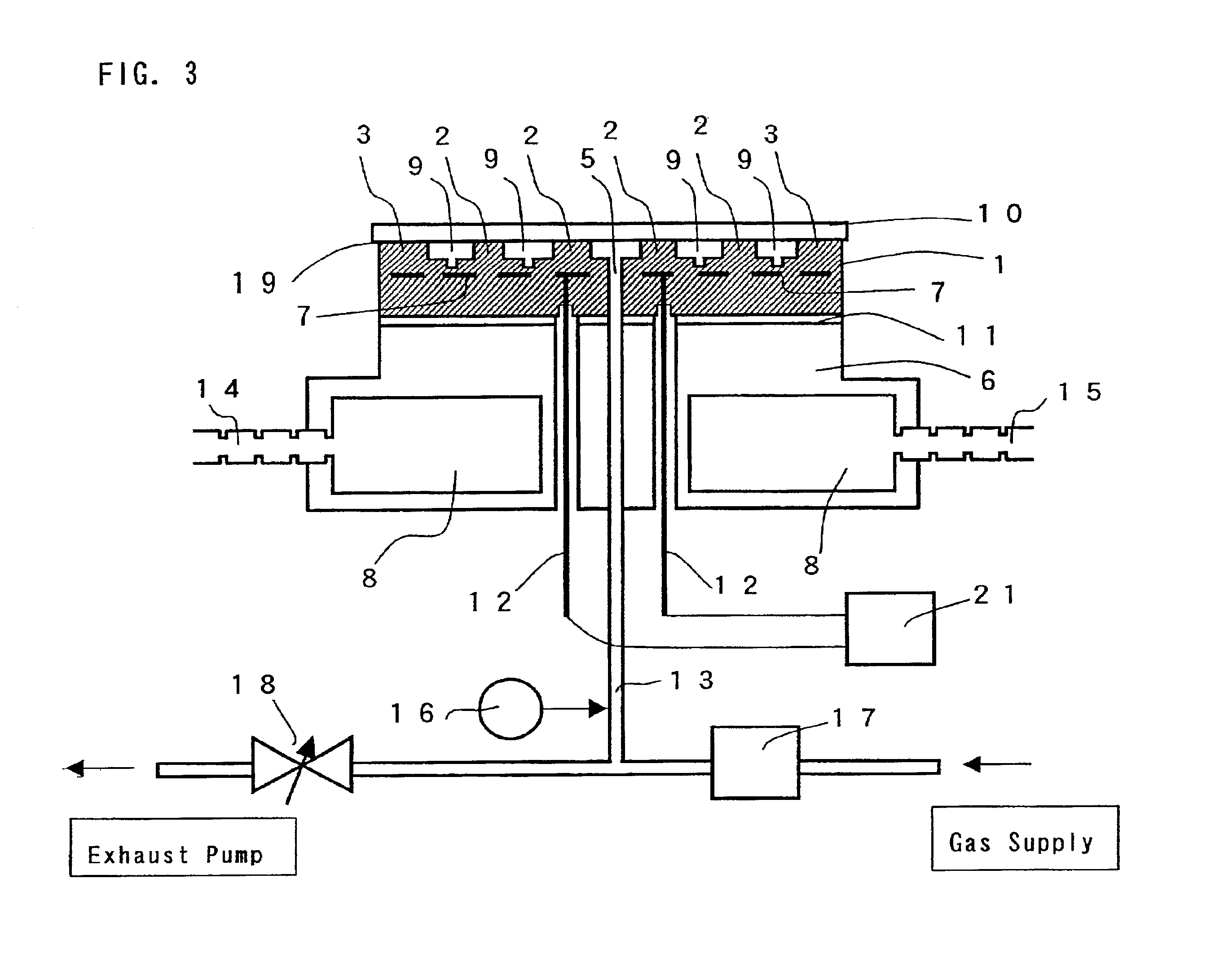
In an embodiment shown in FIG. 2, a dielectric layer la and an insulative support base plate 1b are comprised of the same material, and integrally formed with a layer-laminated structure. FIG. 3 is a cross-sectional view showing the condition of attracting an insulative substrate 10 by an electrostatic chuck 1. By applying voltage to electrodes 7 through conductors 12 for applying voltage, an attracting force is generated between the insulative substrate 10 and the electrostatic chuck 1, thereby attracting the insulative substrate 10 at protrusions 2 and an outer peripheral seal ring 3 (hereinafter, collectively referred to as a "solid-body contact portion"). Also, the electrostatic chuck 1 is connected through ...


PUM


Abstract

An electrostatic chuck for attracting an insulative substrate, used under a vacuum atmosphere, comprises: a dielectric layer having a first surface which attracts an insulative substrate, and a second surface on which are provided a plurality of electrodes; an insulative support base plate fixing the dielectric layer thereon; a plurality of electrically conductive terminals provided on the insulative support base plate; and an electrical connection between the electrodes and the electrically conductive terminals.

Description

1. Field of the InventionThe present invention relates to a processing apparatus of an insulative substrate for use in a PDP (plasma display) manufacturing apparatus, a master writer manufacturing apparatus for a DVD (digital video (or versatile) disc), a substrate processing apparatus for a hard disc manufacturing apparatus, a reticle fixing apparatus in an EB (electron beam) exposure apparatus, and a CVD, etching or sputtering apparatus for manufacturing elements to be formed on SOS (silicon on sapphire) and SOI (silicon on insulator) wafers.2. Description of Prior ArtIn the manufacturing apparatuses for such as a DVD, a PDP or the like, a material to be processed is a glass substrate which shows electrically insulative characteristic. Therefore, in the conventional art, since it is impossible to electrostatically attract these substrates within a vacuum, they are flatly placed on a stage in the manufacturing apparatus thereof or they are fixed with a mechanical mechanism.A reticl...

Claims


Application Information

Patent Timeline
IPC IPC(8): B23Q3/15B23Q3/154H01L21/683H01L21/67H02N13/00
CPCB23Q3/15B23Q3/154H01L21/6833H02N13/00H01L21/68
Inventor KITABAYASHI, TETSUOHORI, HIROAKIUCHIMURA, TAKESHITATENO, NORIAKIFUWA, KOHMAEHIRA, KEN
Owner ULVAC INC
Why Eureka
Try Eureka