Magnetic resonance gradient coil with a heat insulator disposed between the electrical conductor and the carrier structure

a gradient coil and magnetic resonance technology, applied in the field of electric coils, can solve problems such as poor quality of magnetic resonance images, and achieve the effects of efficient cooling effect, disadvantageous effect on surrounding carrier structures, and efficient thermal conductivity of conductors

Inactive Publication Date: 2004-08-10
SIEMENS HEALTHCARE GMBH
View PDF31 Cites 44 Cited by
  • Summary
  • Abstract
  • Description
  • Claims
  • Application Information

AI Technical Summary

Benefits of technology

In another embodiment, the component of the cooling device is fashioned for cooling at least one section of the conductor. As a result of the efficient thermal conductivity of the conductor, for example when the conductor is composed of cooper or aluminum, the component of the cooling device is only sufficient for one section of the conductor in order to obtain an efficient cooling effect for a larger section of the conductor. Sections of the conductor, which are not provided with the component of the cooling device, exhibit heat insulation given the aforementioned cooling by sectors. As a result, temperatures and temperature fluctuations, which occur in heat-insulated conductor sections being comparably far away from the location of cooling and which are greater compared to the cooling location, do not have a disadvantageous effect on the surrounding carrier structure. On the basis of the aforementioned cooling, which is only fashioned in sections, a correspondingly simple cooling device can be fashioned.
For this purpose, the section to be cooled of the conductor, in an embodiment, extends in an edge region of a spatial expanse of the coil, for example, given a spatial expanse corresponding to a hollow cylinder, in a region of a front side of the hollow cylinder. As a result of simple accessibility and short runs, the cooling device can be particularly simply and economically fashioned. Furthermore, space is available for other components in a central area.
In a further embodiment, the heat insulator encloses the conductor. A heat insulation of the conductor from all sides is thus achieved.

Problems solved by technology

The heat build-up in the conductor of the gradient coil leads to a change in temperature of the passive shim device, so that the homogeneity of the basic magnetic field and therefore the quality of magnetic resonance images is impaired.

Method used


Image

  • Magnetic resonance gradient coil with a heat insulator disposed between the electrical conductor and the carrier structure
  • Magnetic resonance gradient coil with a heat insulator disposed between the electrical conductor and the carrier structure
  • Magnetic resonance gradient coil with a heat insulator disposed between the electrical conductor and the carrier structure

Examples


first embodiment

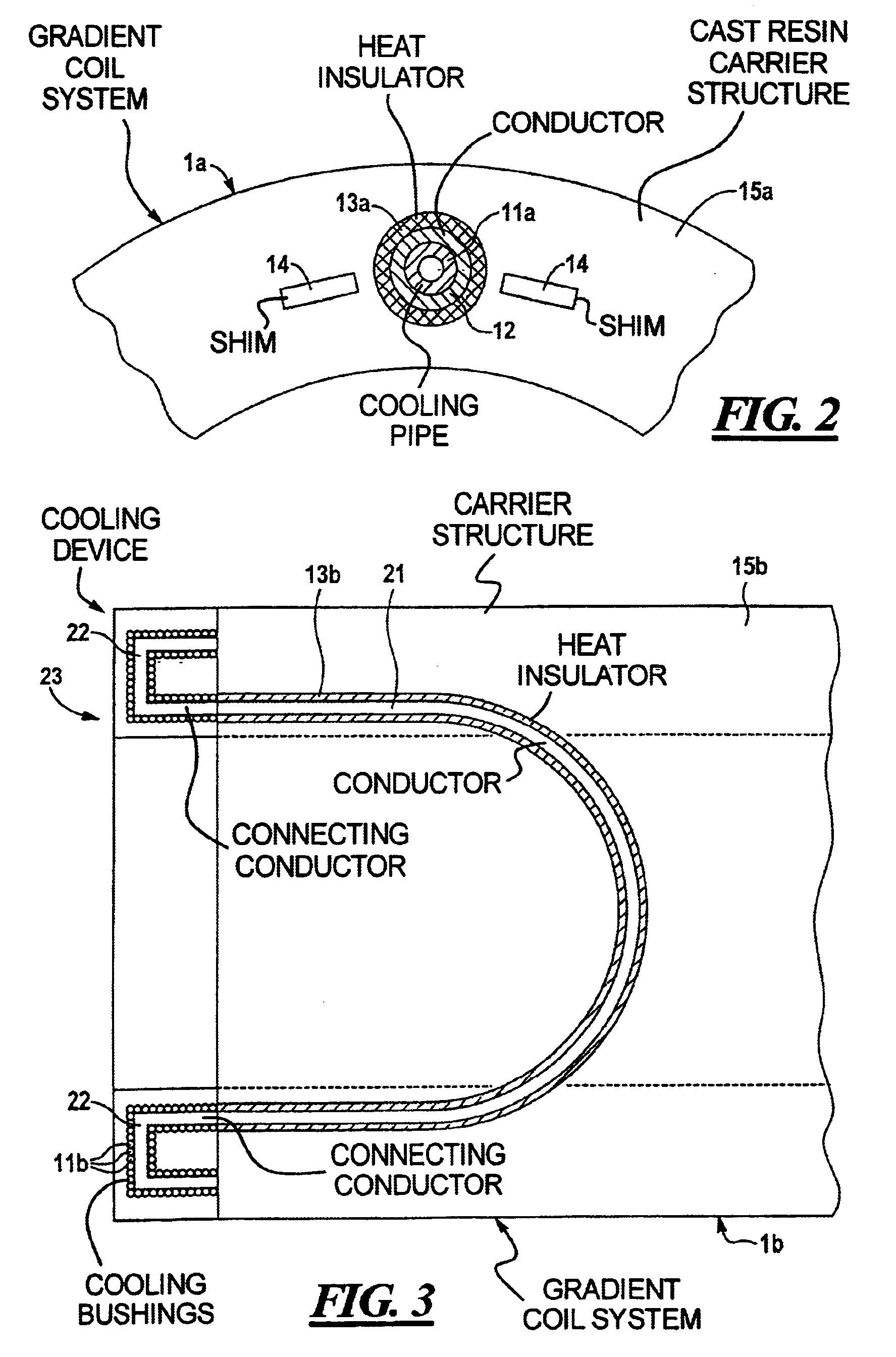
As an exemplary embodiment, FIG. 2 shows a longitudinal section through a hollow cylindrical gradient coil system 1a.

A cross-section of an electrical conductor 12 of a gradient coil, as well as elements 14 for reducing non-homogeneity of the static basic magnetic field are shown enlarged. The electrical conductor 12, for example from copper or aluminum, is fashioned so as to be hollow cylindrical. A cooling pipe 11a, through which a cooling medium such as water can be guided for purposes of cooling the conductor 12, extends within the hollow cylindrical conductor 12 as a component of a cooling device. The cooling pipe 11a is fashioned from an electrically non-conducting material or only slightly conductive material, such as a flexible plastic.

A heat insulator 13a enclosing the conductor 12 is arranged between the electrical conductor 12 and a carrier structure 15a of the gradient coil system 1a, for example a cast resin. The heat insulator is fashioned of fibers and / or high-resistan...

second embodiment

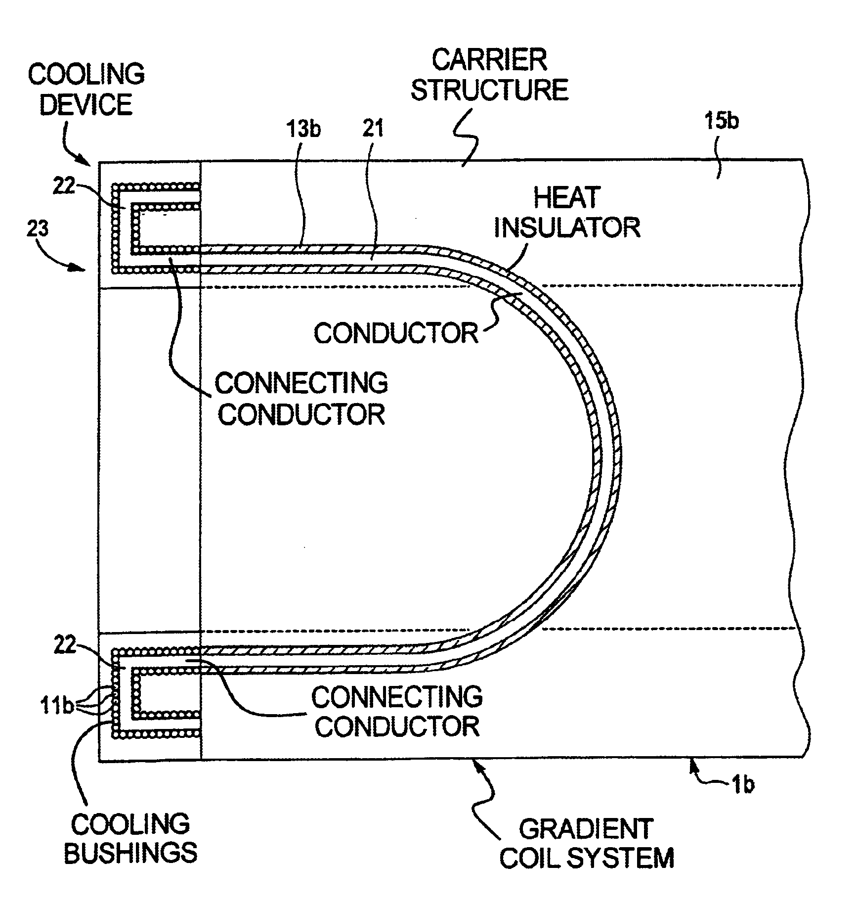
As another exemplary embodiment of the invention, FIG. 3 shows a side view of a hollow cylindrical gradient coil system 1b. Only a horseshoe-shaped conductor section 21 of a primary gradient coil is represented as an example for a cylinder jacket-shaped plane of the gradient coil system. This conductor section 21 is completely enclosed from a heat insulator 13b. At a front side of the hollow cylindrical gradient coil system 1b, the horseshoe-shaped conductor section 21 is connected to a further horseshoe-shaped conductor section (not shown) of a corresponding secondary coil by means of connecting conductors 22. Conductors of the secondary coil are also arranged in a cylinder jacket-shaped plane concentrically surrounding the cylinder jacket-shaped plane of the primary gradient coil. The connecting conductors 22 of the gradient coil at the front side can be cooled by being surrounded by cooling bushings 11b as components of a cooling device, with tight packing. A cooling medium can b...


PUM

PropertyMeasurementUnit
thermal conductivityaaaaaaaaaa
electrical conductoraaaaaaaaaa
electricalaaaaaaaaaa

Abstract

An electrical coil, particularly a gradient coil for a magnetic resonance apparatus, contains at least one electrical conductor, a carrier structure, at least one component of a cooling device and a heat insulator, which is arranged for at least one section of the conductor between the conductor and the carrier structure.

Description

BACKGROUND OF THE INVENTION1. Field of the InventionThe present invention relates to an electrical coil, particularly a gradient coil for a magnetic resonance apparatus.2. Description of the Prior ArtThe technical range of application of electrical coils is versatile. In many designs, an electrical coil has a casting, for example from a artificial resin, in order to, among other things, obtain a high insulating strength and a high structural strength. Moreover, it is known to cool an electrical coil during operation of the coil in order to, among other things, increase the efficiency. For this purpose, a cooling device, for example, transports heat arising in a conductor of the coil as a result of a current flow out of the coil.A highly stressed electrical coil is a gradient coil of a magnetic resonance apparatus, for example. Among other things, the magnetic resonance apparatus has a gradient coil system for generating rapidly switched gradient fields, as well as a basic field magn...

Claims


Application Information

Patent Timeline
Patent Type & Authority Patents(United States)
IPC IPC(8): G01R33/385G01R33/38H01F5/00A61B5/055G01R33/3873
CPCG01R33/3856H01F5/00
Inventor HEID, OLIVER
Owner SIEMENS HEALTHCARE GMBH
Why Eureka
Try Eureka