Micro-structured optical fibers

a technology of optical fibers and microstructures, applied in the field of stepindex optical fibers, can solve the problems of limiting the length of pcfs that can be produced, central defects may be created, and central defects can be created

Inactive Publication Date: 2004-08-10
NORTEL NETWORKS LTD
View PDF11 Cites 4 Cited by
  • Summary
  • Abstract
  • Description
  • Claims
  • Application Information

AI Technical Summary

Benefits of technology

Having solid cores or core preforms overcomes many of the difficulties previously associated with the size reduction process in micro-structured optical fibre fabrication. For example, the absence of air channels during the process means that the problems of channel collapse and fibre fragility are negated, and core size can be controlled with relative ease. Overall, uniformity can be attained over much longer lengths of fibre. However, if the fibre is ultimately to have air channel periodic features, a method is required of removing the solid cores.

Problems solved by technology

In the case of solid core PCFs, a central defect is created by removing or altering hole(s) along the length of the fibre at the centre.
In the case of hollow core PCFs, the central defect may be created by an oversized hole.
However, the difficulties associated with making PCFs by such methods, notably in terms of maintaining cleanliness and uniformity and the associated resolution issues, means that there is a limit on the length of PCFs that can be produced.
Uniformity is a particular problem, and unless the size reduction process is very carefully controlled, hole collapse may occur, leading to distortion.
Current PCFs are limited to two dimensional lattice structures because no known method has been proposed to make the periodic features anything other than continuous along the whole length of the fibre material.
At present, use of PCFs is limited to optical gain, harmonic generation, continuous generation and enhanced fibre lasers.
It is not possible to write a Bragg grating into an air core and the introduction of an active material in the air core region destroys the photonic band gap confinement.

Method used


Image

  • Micro-structured optical fibers
  • Micro-structured optical fibers
  • Micro-structured optical fibers

Examples


Embodiment Construction

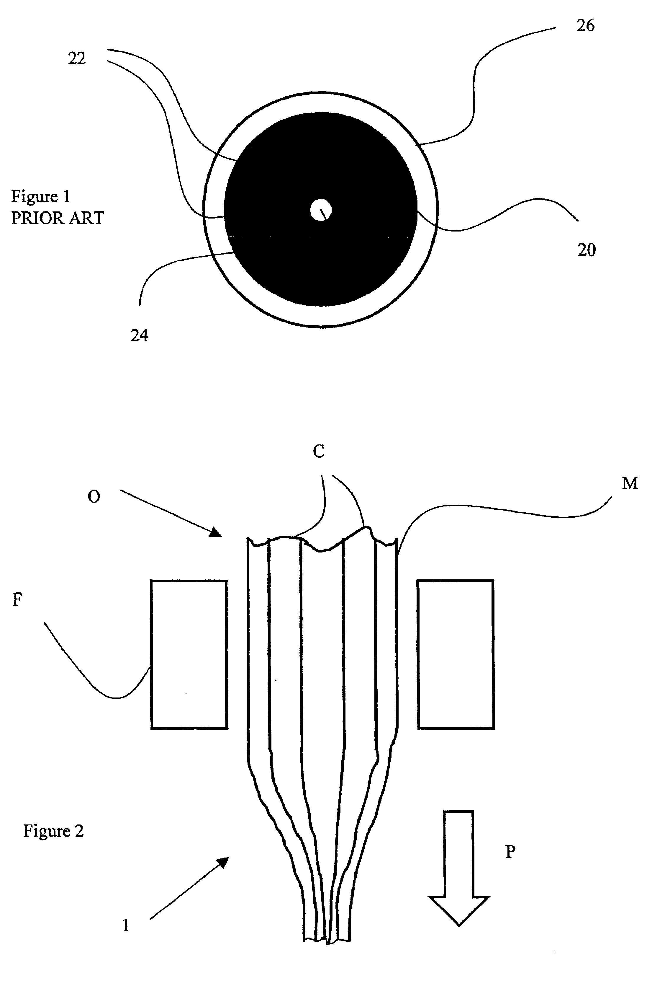
With reference to FIG. 2, a multiple core optical fibre preform O is provided by fusing together parallel strands of core material C and a cladding material M so as to embed the cores in the cladding. The preform O, with its multiple core preforms C, is then size reduced down to the required dimensions by heating it until plastic and pulling one end. The preform is heated in a furnace F and pulled in the direction shown by the arrow P.

A micro-structured optical fibre precursor is made by either pulling the multiple core optical fibre preform O so as to size reduce it on one operation, or in a separate operation, a multiple core optical fibre, having previously been fabricated, is heated and pulled so as to size reduce it. The precursor is encased in a jacket.

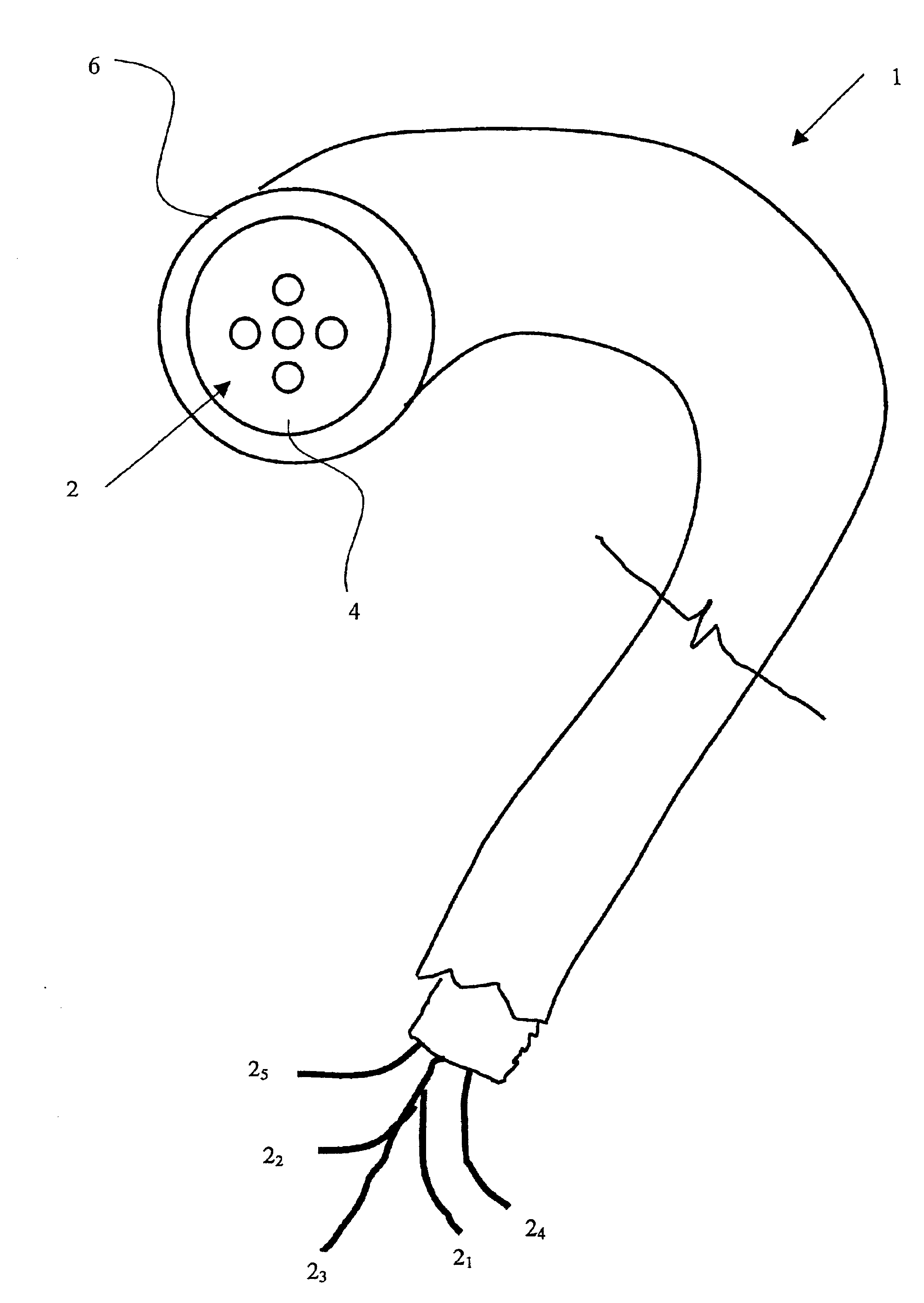
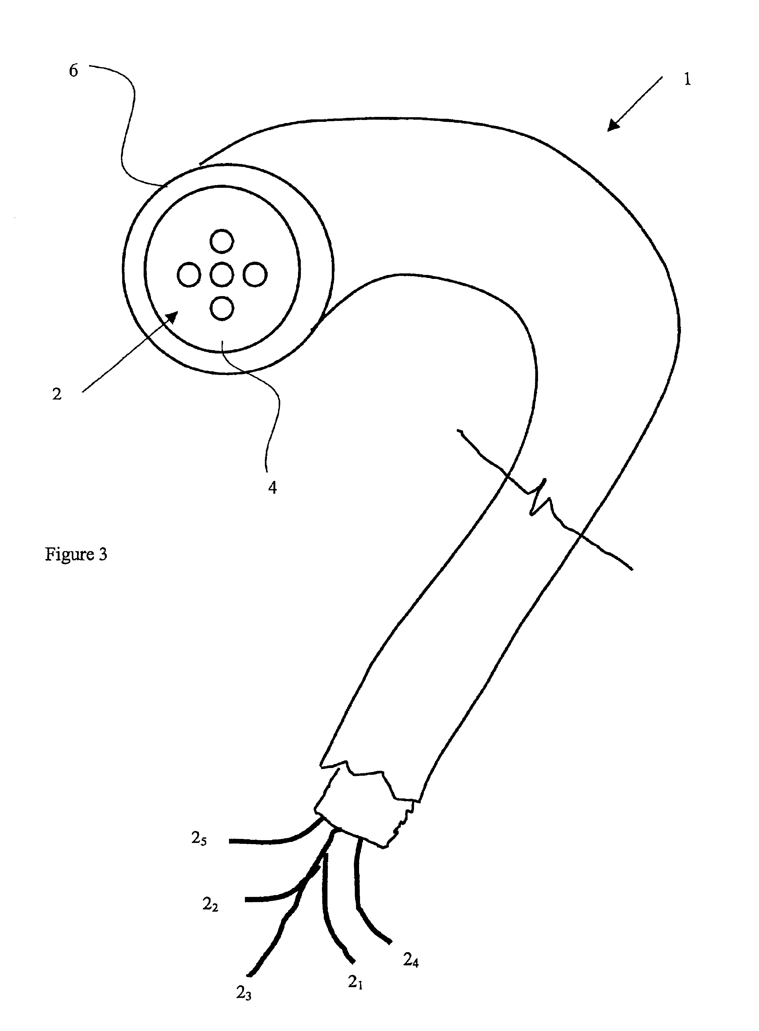
With further reference to FIG. 3, a micro-structured optical fibre precursor 1 has five solid multiple cores 2 (for the purpose of illustration only five cores 2 are shown) surrounded by a cladding 4 encased in a jacket 6. The p...


PUM

PropertyMeasurementUnit
lengthaaaaaaaaaa
poweraaaaaaaaaa
lengthaaaaaaaaaa

Abstract

A micro-structured optical fiber precursor 1 is made by size reducing a multiple core optical fiber having solid multiple cores or a multiple core optical fiber preform O having multiple solid core preforms C. A fiber fuse is induced in at least one of the cores 2 of the precursor 1. The effect of the fiber fuse is to consume the core 2 along the whole length of the fiber or to consume periodically spaced lengths of core 2 along the whole length of the fiber.

Description

The invention relates to a class of micro-structured optical fibres known as photonic crystal fibres (PCFs), holey fibres (HFs) and generic micro-structured optical fibres and to methods of making them. Optical fibres are used, for example, in optical communications networks to carry optical communication signals.BACKGROUND TO THE INVENTIONConventional step-index optical fibres typically comprise a central core of relatively high refractive index material, surrounded by a cladding of relatively low refractive index material, encased in a protective jacket. Light is confined to the core by total internal reflection as a result of the step difference in refractive index between the core and the cladding.In contrast to conventional step-index fibres, PCFs and HFs typically comprise one material that is provided with periodic features in the cross section of the fibre, transverse to the propagation direction. These features are generally air holes which run along the length of the fibre...

Claims


Application Information

Patent Timeline
Patent Type & Authority Patents(United States)
IPC IPC(8): C03B37/012G02B6/02
CPCC03B37/01225C03B37/01228C03B37/01231C03B37/0124G02B6/02376C03B2201/34C03B2203/14C03B2203/16C03B2203/18C03B2203/34C03B2203/42G02B6/02366
Inventor MARONEY, ANDREW VREYNOLDS, ANDREW LCORDINA, KEVIN JTASTAVRIDIS, KOSTAS
Owner NORTEL NETWORKS LTD
Why Eureka
Try Eureka