Bushing arrangement

a technology of abushing and abushing paste, which is applied in the direction of conductive materials, non-conductive materials with dispersed conductive materials, conductive materials, etc., can solve the problems of reducing the degree to which electricity can flow through the moulding paste to earth or ground, affecting the protection provided against electromagnetic overtension, and exhibiting a relatively high electrical resistance valu

Inactive Publication Date: 2004-08-17
BEELE ENG
View PDF6 Cites 20 Cited by
  • Summary
  • Abstract
  • Description
  • Claims
  • Application Information

AI Technical Summary

Problems solved by technology

One drawback of the bushing arrangement that is disclosed in the aforesaid Dutch patent application is the fact that it has become apparent in practice that in some cases the moulding paste exhibits a relatively high electrical resistance value, in the order of about 100-100 Ohm, after curing.
In particular this means that the degree to which electricity can flow away to earth or ground via the moulding paste has decreased considerably, which has an adverse effect on the extent of protection that is provided against electromagnetic overtension.
Electrical installations and machines, which usually include highly sensitive components, for example for control and registration purposes, can easily experience interference caused by various external electromagnetic (em) fields and pulses.
Electrical cables that are passed into such a screened space can conduct undesirable electromagnetic fields and pulses into the electronic equipment, however.

Method used


Image

  • Bushing arrangement
  • Bushing arrangement
  • Bushing arrangement

Examples


Embodiment Construction

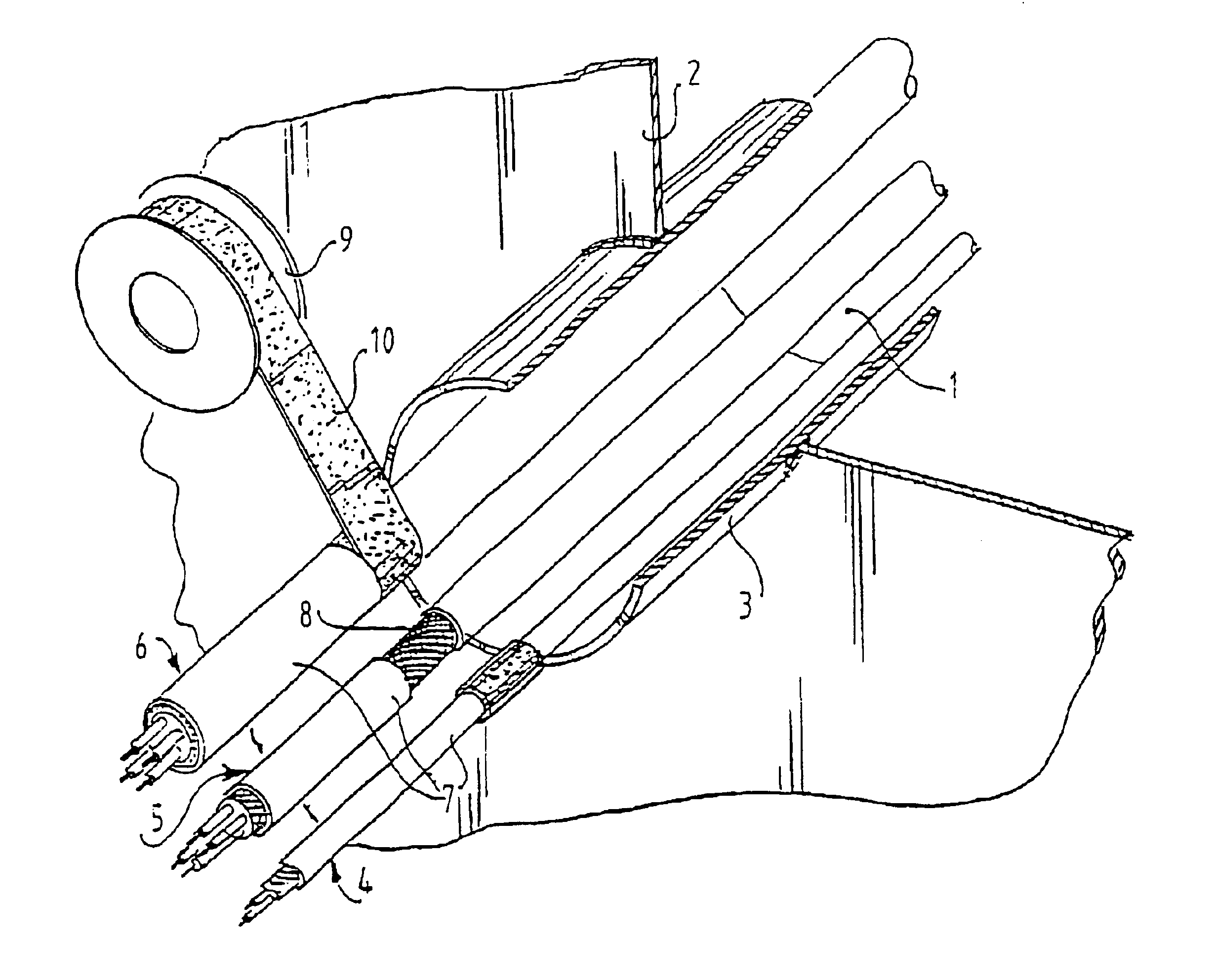
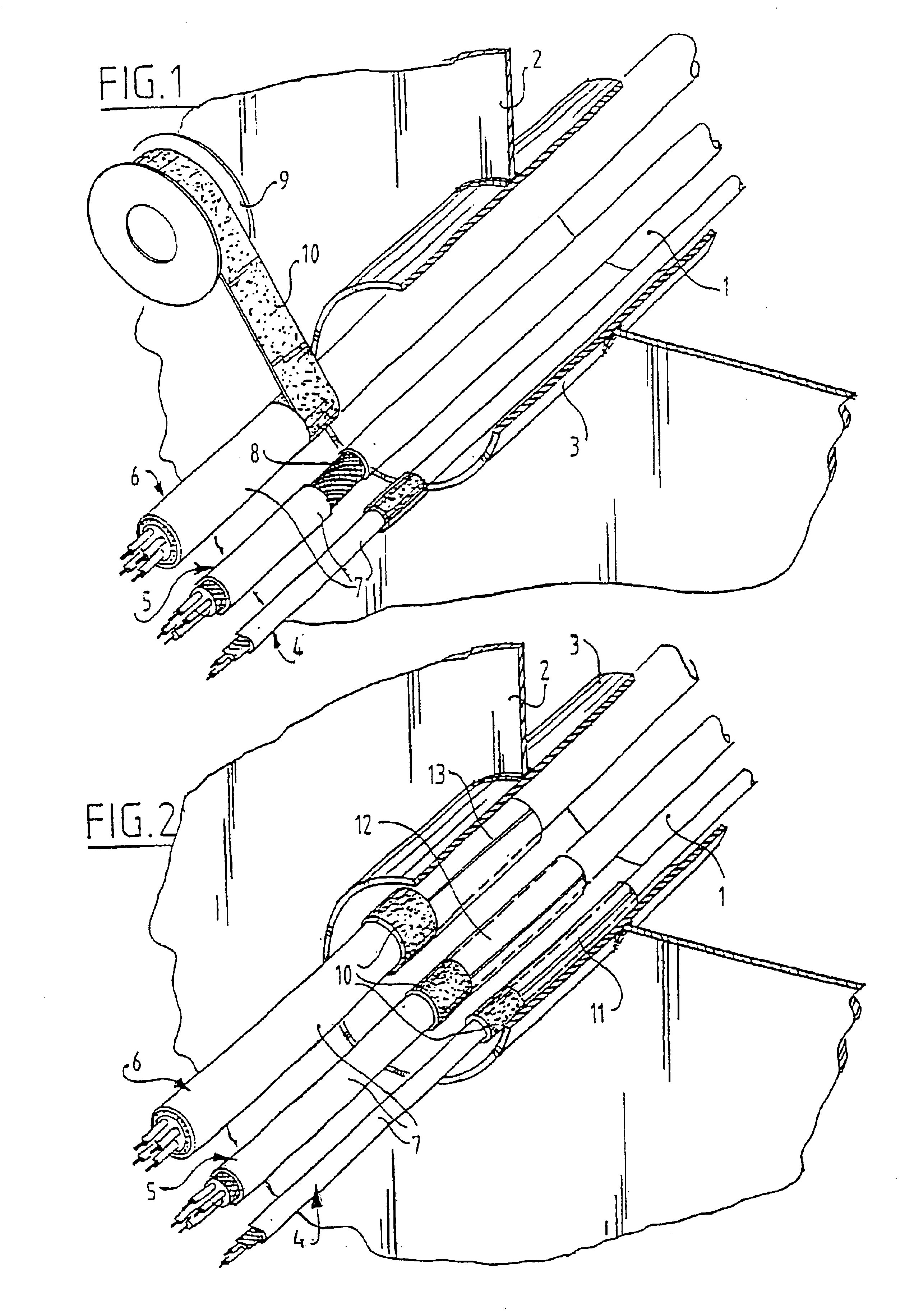
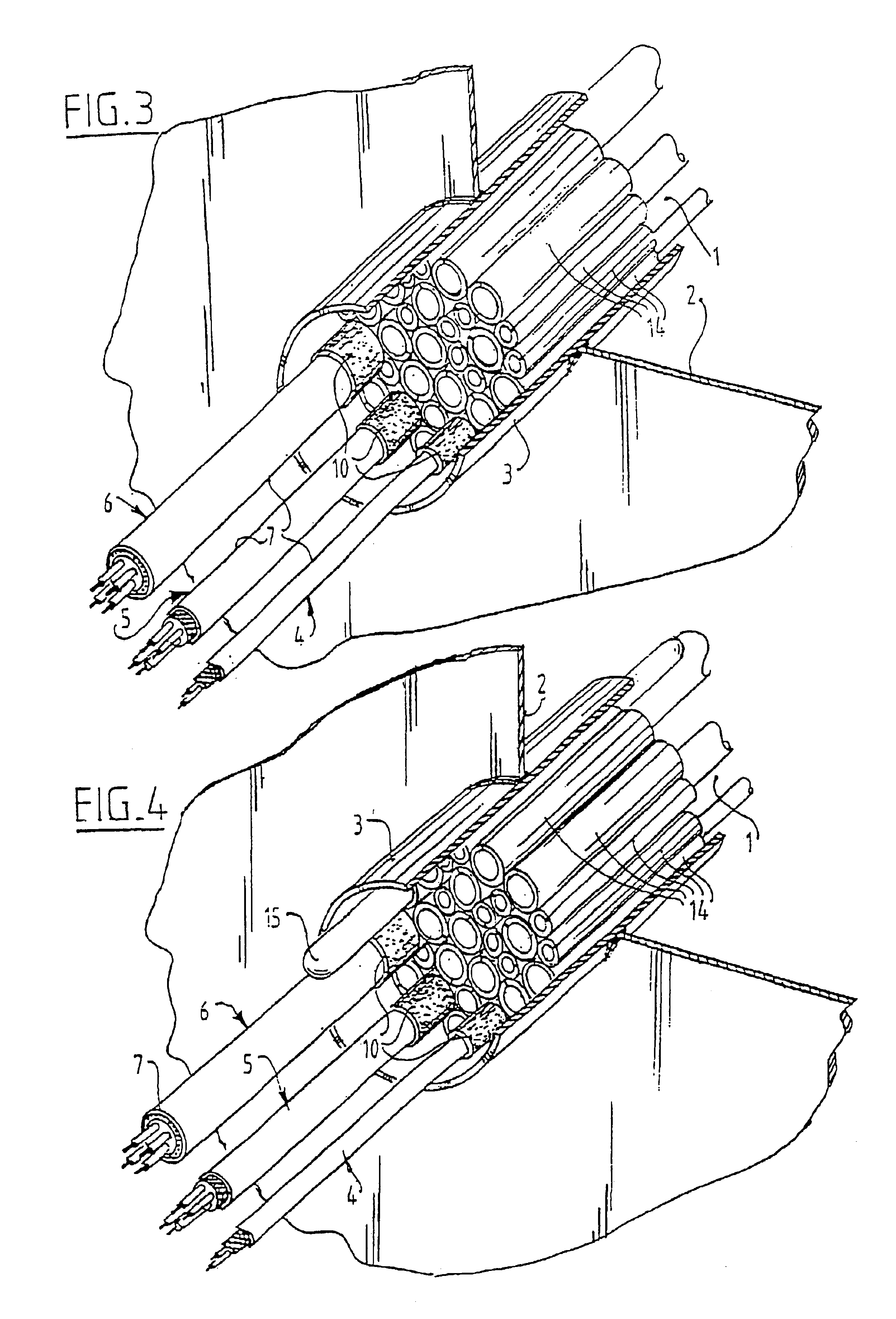
FIG. 1 shows an opening in a wall 2, in which a steel bushing housing 3 is mounted. For the sake of simplicity, only three multi-core cables 4, 5, 6 are shown in the drawing, which cables have each been stripped of their plastic sheathing 7 along part of their length, so that their electrically conductive shielding (braid) 8 is now exposed. In accordance with the invention, a tape 10 of EPDM rubber on a winding roll 9 is used, which tape has been made electrically conductive by the chemical addition thereto of carbon particles, for example carbon black particles having concave, shell-shapes, which tape is to be wound round the electrically conductive cable shielding 8. Tape 10 preferably has a width of 40 mm, so that an optimum electrically conductive contact with the electrically conductive cable shielding 8 is realised. The electrical earthing is ensured by winding tape 10 to a diameter larger than that of cables 4, 5, 6, as is shown in FIG. 1 and as will be explained in more deta...


PUM


Abstract

A bushing arrangement and method for passing an electrical cable with conductive shielding through an opening in a wall while providing protection against electromagnetic overtension and electrical interference and the like, including the placement of an electrically conductive bushing in the wall opening that is electrically connected to earth ground potential, and electrically connecting an electrically conductive tape between the electrically conducting shielding and the electrically conductive bushing so as to connect the conductive shielding to earth ground potential. The electrically conductive tape is made electrically conductive by the use of carbon black particles.

Description

Not applicable.REFERENCE TO A "SEQUENCE LISTING"Not Applicable.1. Field of the InventionThe invention relates to a bushing arrangement and method for passing cable through an opening in a wall, plating, partition and the like, such as a bulkhead of a ship, for example while providing protection against electromagnetic overtension and / or interference. Hereinafter, the term "wall" will be used for the sake of simplicity, while this term is understood to include other partitions as well.2. Description of the Related ArtA bushing arrangement is disclosed in Dutch patent application no. 1011718 in the name of the present applicant. The bushing arrangement that is disclosed therein consists of a steel bushing fitted in a wall opening, through which a number of single-core or multiple-core steel bushing fitted in a wall opening, through which a number of single-core or multiple-core cables are passed. The cables are stripped of their sheathing along a suitable part of their length, so that...

Claims


Application Information

Patent Timeline
Patent Type & Authority Patents(United States)
IPC IPC(8): H02G3/22H05K9/00
CPCH02G3/22H05K9/0018
Inventor BEELE, JOHANNES ALFRED
Owner BEELE ENG
Why Eureka
Try Eureka