Superconducting magnetic apparatus

a superconducting magnetic and apparatus technology, applied in the direction of superconducting magnets/coils, instruments, magnetic bodies, etc., can solve the problems of complex mechanical structure, large leakage of magnetic fields outside the apparatus, and the region (clear bore) for accommodating gradient magnetic coils (gcs) and high frequency coils (rf coils) cannot be effectively utilized, so as to facilitate on-the-spot assembling and adjustment of magnetic field distribution correction, the effect of improving th

Inactive Publication Date: 2004-08-24
HITACHI MEDICAL CORP +1
View PDF15 Cites 18 Cited by
  • Summary
  • Abstract
  • Description
  • Claims
  • Application Information

AI Technical Summary

Benefits of technology

In this configuration, the magnetic field correcting means are circular. This brings about effects of fine workability, cost reduction, and a large correction effect.
As heretofore described, it becomes possible according to the present invention to reduce the labor required for assembling and adjustment work at the time of supply of a superconducting magnet apparatus for MRI apparatus, reduce the manufacturing cost owing to the simplified structure, and provide a superconducting magnet apparatus for MRI apparatus improved in magnetic field homogeneity by utilizing the gap between the superconducting magnet and the magnetic shield.

Problems solved by technology

In the static magnetic field generating apparatus, there occurs a problem that a lot of magnetic fields leak outside the apparatus because a high static magnetic field is generated in the imaging space.
As a result, the region (clear bore) for accommodating gradient magnetic coils (GCs) and a high frequency coil (RF coil) cannot be utilized effectively.
The increase in the magnetomotive force causes a complicated mechanical structure and an increased cost, resulting in a serious problem.
As heretofore described, the conventional magnetic field generating apparatus had a problem that an attempt to correct the inhomogeneous magnetic field in the static magnetic field caused an increased region for correction, an increased size of external shape of the apparatus, and an increased manufacturing cost.
Furthermore, it was also difficult for an inspector to access the subject from the outside of the apparatus.
In the case where the intensity of the pulsative magnetic field is intense, however, a sufficient effect cannot be obtained.
Therefore, there is a problem that the access to the subject from the outside of the apparatus is difficult.
Furthermore, there is a problem that the subject feels oppression because the subject is in the magnet and the view in the transverse direction is obstructed.
This results in a problem that it is difficult to increase the magnetic field intensity in the homogeneous magnetic field generation region 2, and, in the case of high magnetic field, it is also difficult to decrease the magnetic field leakage outside the apparatus.
Therefore, giving treatment to the subject and coping with the IVMR (Interventional MR) vigorously developed in recent years were also difficult.
In this MRI apparatus, however, it is difficult to achieve a high magnetic field and it is necessary to further improve the magnetic field intensity to realize a high picture quality.
As the magnetic field intensity is increased, however, the superconducting magnet apparatus for MRI apparatus having such a structure tends to become large in size and weight.
After the magnetic shield has been assembled, therefore, it is impossible to insert the superconducting magnets from the transverse direction.
After inserting the superconducting magnets in the magnetic shield and fixing the superconducting magnets, therefore, these magnetic field homogenizing means 32 must be fixed, resulting in a very poor work efficiency.
Assembly using this method is not an easy work for the magnetic shield made large in size.
Furthermore, in the case where the superconducting magnet is divided and assembled on the spot, the reproducibility of the magnetic field adjustment in the factory is not maintained and fine adjustments were needed on the spot.

Method used


Image

  • Superconducting magnetic apparatus
  • Superconducting magnetic apparatus
  • Superconducting magnetic apparatus

Examples


Embodiment Construction

Hereafter, embodiments of the present invention will be described concretely by referring to accompanying drawing.

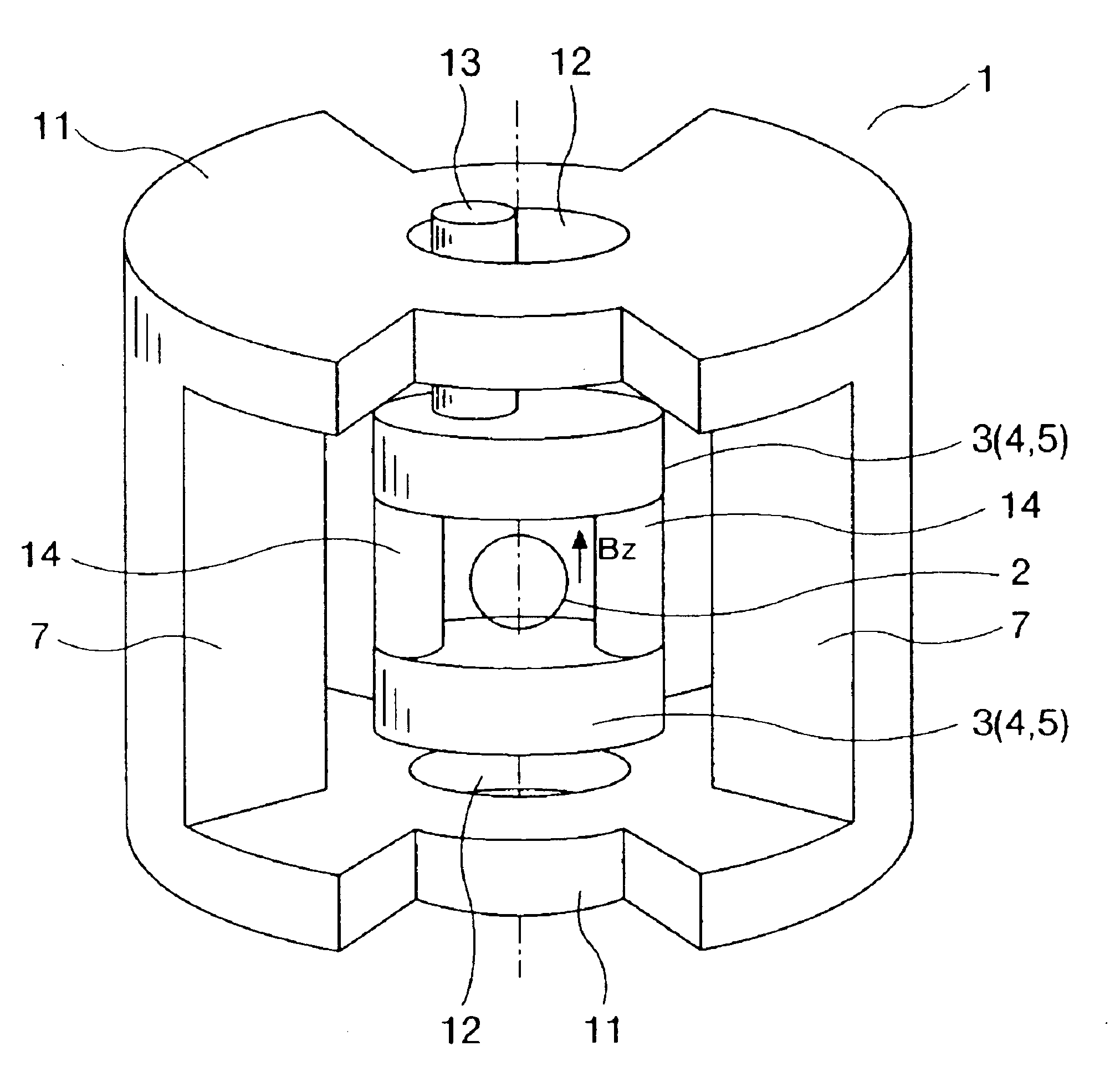
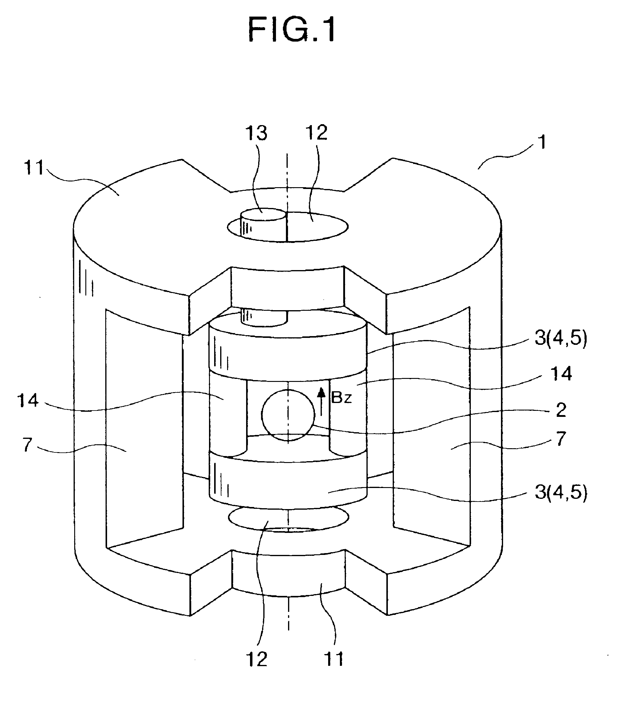
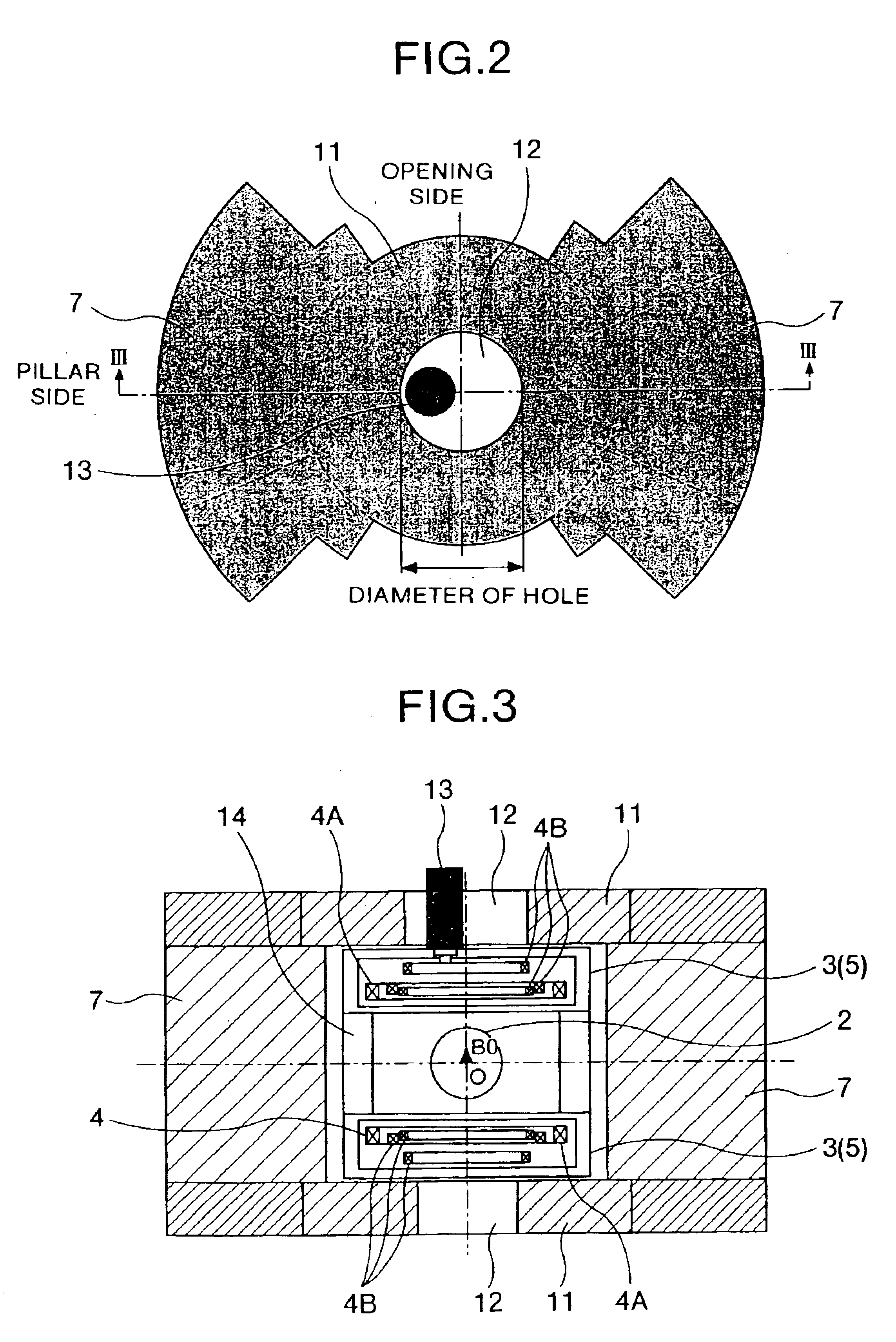
An embodiment of a static magnetic field generating apparatus generating a homogeneous static magnetic field is shown in FIGS. 1 to 3. FIG. 1 is its entire oblique view. FIG. 2 is its top view. FIG. 3 is its longitudinal section view. A static magnetic field generating apparatus (superconducting magnetic apparatus) 1 of the present embodiment has superconducting magnets of the vertical magnet field system. First of all, static magnetic field generating sources (superconducting magnets) 3 incorporating superconducting coils 4 for generating a static magnetic field in an imaging space 2 are disposed above and below the imaging space 2 so as to be opposed to each other. Each of the superconducting coils 4 is held in a cooling vessel 5, and cooled to such a temperature that a predetermined superconducting characteristic is obtained. The superconducting coil 4 is typically fo...


PUM

PropertyMeasurementUnit
viewing angleaaaaaaaaaa
hole diameteraaaaaaaaaa
radiusaaaaaaaaaa

Abstract

A superconducting magnet apparatus. By forming one or more holes in each of platelike ferromagnetic substances forming a magnetic shield for focusing the magnetic flux generated by superconducting coils, the flow of lines of magnetic flux is adjusted. Thereby, a static magnetic field in a measurement space is corrected. By disposing coupling tubes for supporting two cooling vessels housing superconducting coils on the rear side with respect to a central axis (Z axis) of the measurement space of the vertical direction, access to the subject is facilitated. In addition, the magnetic shield has an opening portion wider than the superconducting magnet on its side face. After the magnetic shield has been assembled, the superconducting magnet can be inserted from the opening portion.

Description

The present invention relates to a static magnetic field generating apparatus used in a magnetic resonance imaging apparatus (hereafter referred to as MRI apparatus) and the like, and in particular to a magnetic field correction means for improving the field homogeneity of the static magnetic field generated by a static magnetic field generating apparatus.Furthermore, the present invention relates to a superconducting magnet apparatus having a wide opening to provide a subject with feeling of openness and facilitate access to the subject.Furthermore, the present invention relates to a superconducting magnet apparatus which can be constructed with ease and high precision after it has been carried in a site of use such as a hospital or a clinic.In the case of MRI apparatuses, characteristics of the static magnetic field are the most important characteristics exert directly upon the image distortion, image blurredness, and signal-to-noise ratio, and the characteristics of the static ma...

Claims


Application Information

Patent Timeline
Patent Type & Authority Patents(United States)
IPC IPC(8): G01R33/38G01R33/383G01R33/3815
CPCG01R33/3806G01R33/3815G01R33/383G01R33/3873
Inventor TAKESHIMA, HIROTAKAHOMMEI, TAKAOKAWANO, HAJIMETAZAKI, HIROSHIYATSUO, TAKESHIKURODA, SHIGENORITANABE, HAJIME
Owner HITACHI MEDICAL CORP
Why Eureka
Try Eureka