
Closing device, in particular for a motor vehicle

Inactive Publication Date: 2004-09-21
STABILUS
View PDF10 Cites 18 Cited by
  • Summary
  • Abstract
  • Description
  • Claims
  • Application Information

AI Technical Summary

Benefits of technology

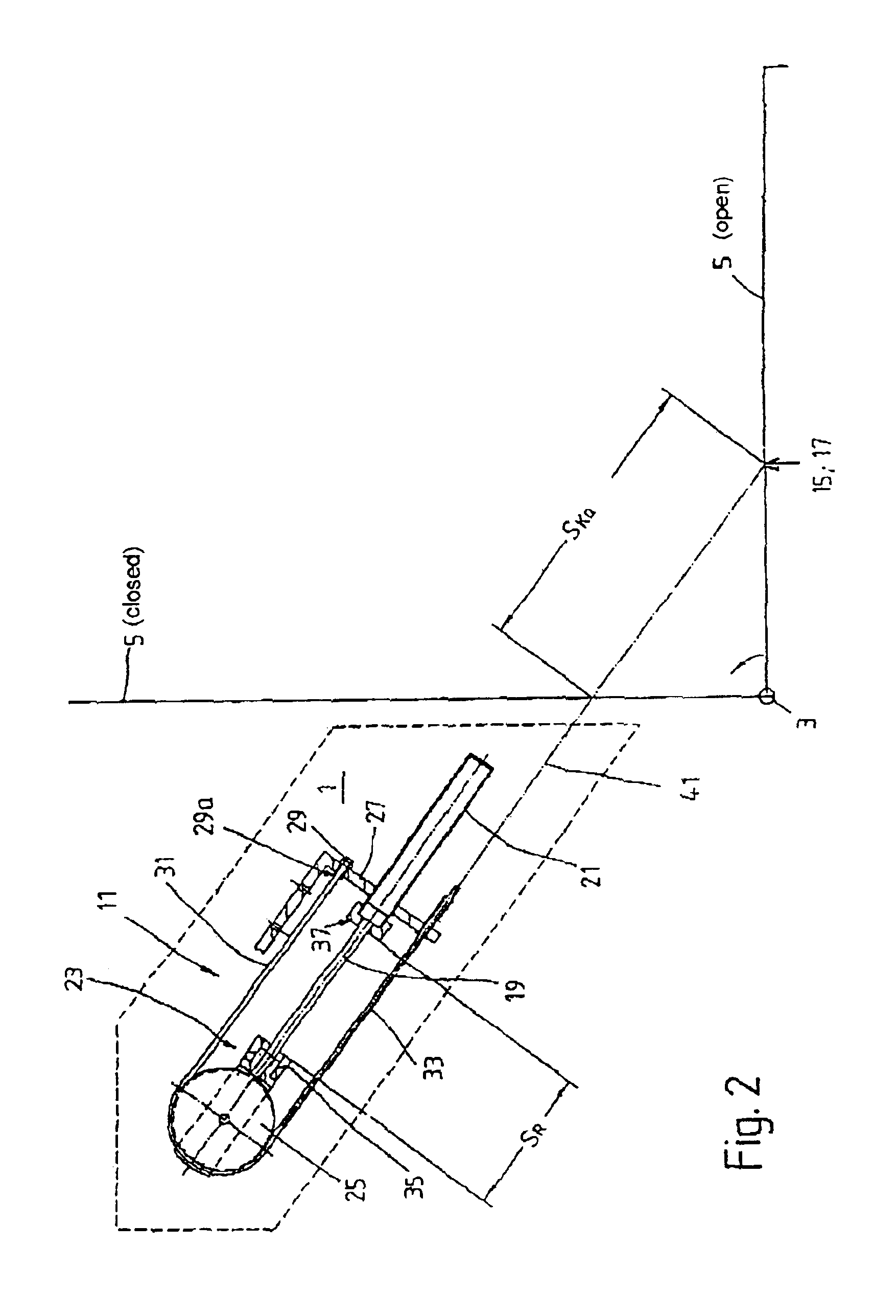
The effect achieved by the axially moveable deflection pulley for the cable device is that the ratio of piston-rod movement to pivoting movement of the body part is 1:2. The fitting of an extremely short spring element is therefore possible.
In one embodiment, the cable device engages on the moveable body part at two supporting points and, at a predetermined angular position of the body part, two sections of the cable device exert a supporting force, with a stop device, as part of the cable device, being in engagement during the closing movement owing to the spring force of the spring element. The effect achieved is that, firstly, the favorable stroke / body-part movement ratio is maintained and, secondly, two supporting points can be used, with the result that the introduction of force into the body part can be undertaken more favorably.
In addition, the stop device can have a stop ring which can be displaced axially on the cable device in order to adjust the stop device. By this means, freedom from play within the closing device during the closing movement is achieved.
As an alternative, two spring elements arranged parallel in their function may also be used, with a single cable device being connected to both spring elements. The favorable movement ratio of spring element and body part is also achieved in this variant. The freedom from play within the closing system arises automatically, since the two spring elements prestress the cable device owing to the directions in which their forces act.

Problems solved by technology

In the case of this construction principle, there is the serious disadvantage that the stroke movement of the piston rod is converted into a pivoting movement of the body part only in the ratio of 2:1.
However, there is virtually no suitable connecting point for this, in particular in the region of the trunk in a motor vehicle.

Method used


Image

  • Closing device, in particular for a motor vehicle
  • Closing device, in particular for a motor vehicle
  • Closing device, in particular for a motor vehicle

Examples


Embodiment Construction

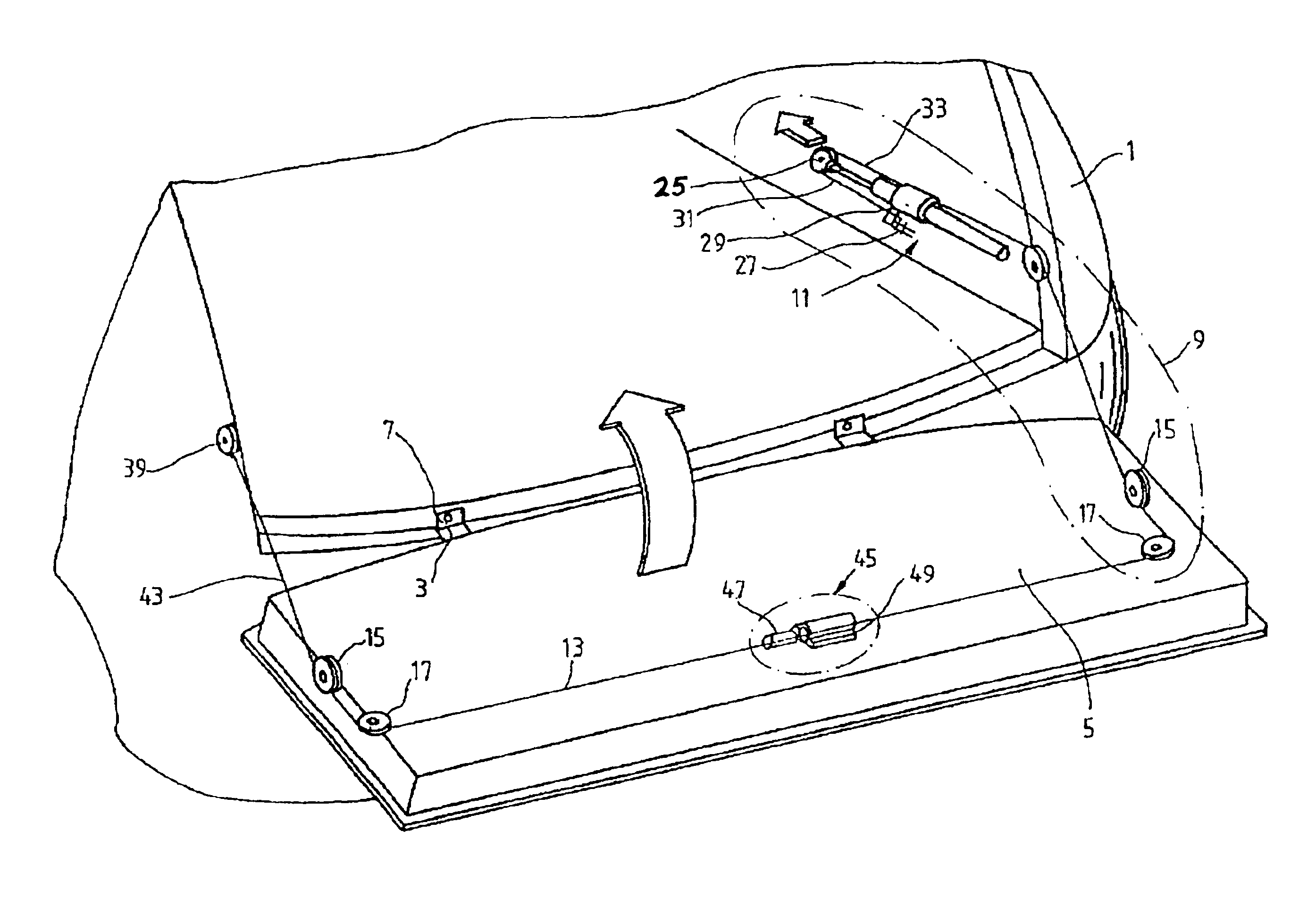
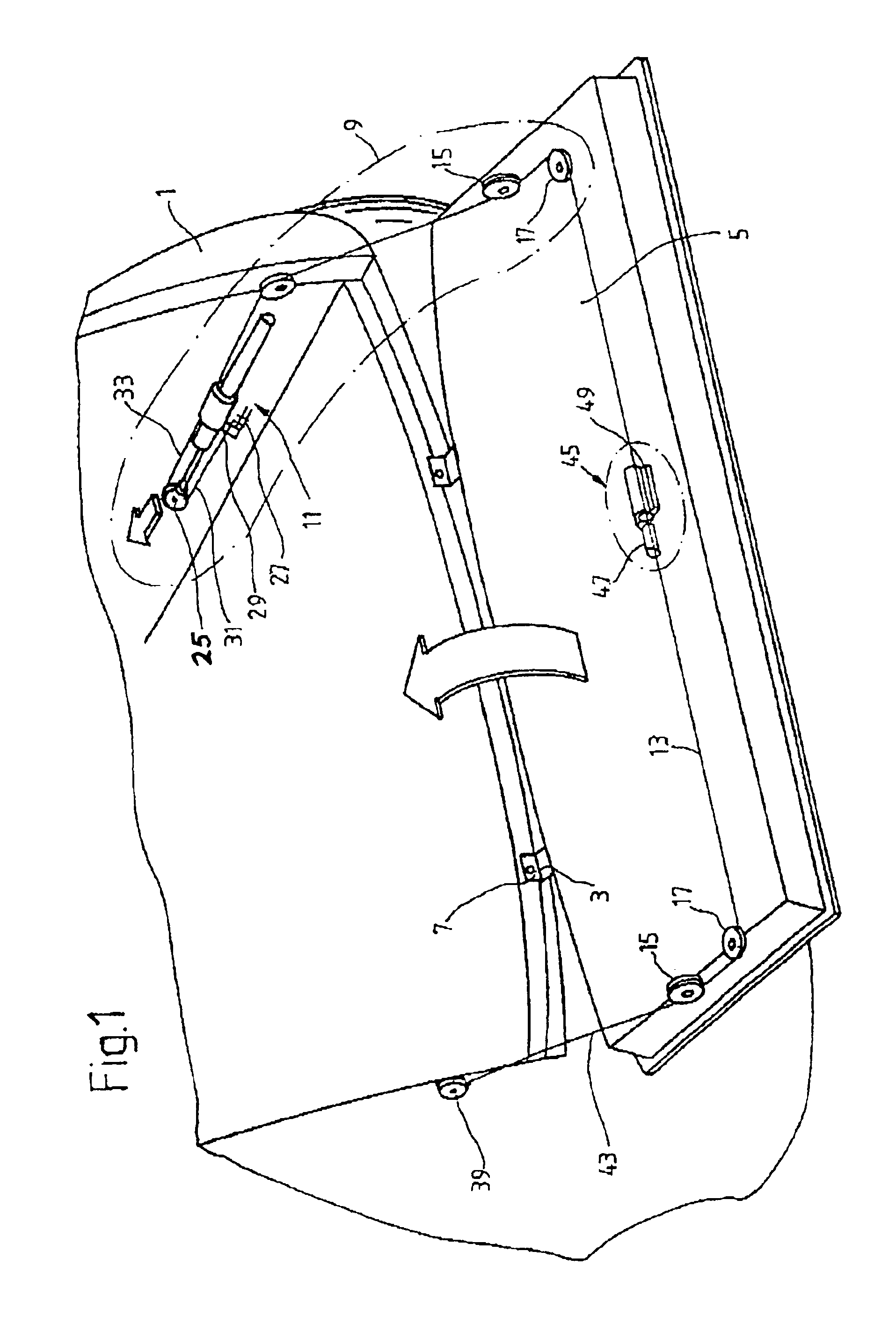
FIG. 1 shows the rear part of a motor vehicle having a base part 1 and a body part 5 which can be pivoted about an axis 3, which runs transversely with respect to the longitudinal axis of the base part. The axis 3 is formed by a number of pivot bearings 7. The body part is, for example, the tailgate of a vehicle.

The tailgate is moved by a closing device 9 in the direction of the arrow from any opened position. The force is introduced starting from a spring element 11 and a cable device 13 which acts on the body part 5 via deflection pulleys 15; 17.

In the overall view of FIG. 2, it can be seen that the spring element 11, as a first subassembly, has an axially moveable piston rod 19 and, as a second subassembly, a cylinder 21 which is positionally fixed with respect to the base part 1. Fastened to the outer end of the piston rod is a connecting head 23 having a deflection pulley 25 over which the cable device 13 is guided. A first end 29 of the cable device is connected to a securing ...


PUM


Abstract

Closing device, in particular for a body part on a motor vehicle, the body part being mounted pivotably on a base part, includes a spring element having a piston rod which is axially moveable within a cylinder to exert a closing force on the body part via a cable device, which engages on the body part. The spring element has, on its piston rod, a deflection pulley over which the cable device is guided, the end of the cable device being fixed with respect to the cylinder.

Description

1. Field of the InventionThe invention relates to a closing device for a body part pivotably mounted on a base part having a spring element including a piston rod which is axially moveable in a cylinder and a cable device which engages the body part.2. Description of the Related ArtFR 2 717 215 A1 describes a closing device, in particular for a body part on a motor vehicle, the body part being mounted pivotably on a base part and a pneumatic spring element having an axially moveable piston rod, as a first subassembly, within a cylinder, as a second subassembly, which exerts a closing force on the body part via a cable device, which engages on the body part.In the exemplary embodiment according to FIG. 3, the cable device comprises two subunits which are actuated in the tension direction by the gas-filled spring. The vehicle flap pivots in the closing direction to the same extent as the piston rod is moved. For an effective transmission of tensile force, the two subunits have to be c...

Claims


Application Information

Patent Timeline
IPC IPC(8): E05F1/10E05F1/00E05F11/04E05F3/02E05F11/00E05F3/00B60J5/10
CPCE05F1/1091E05F1/1058E05F3/02Y10T16/56E05Y2900/546E05Y2900/544E05F11/04
Inventor MULLER, THORSTENROSENSTEIN, BERNDRICH, COLIN
Owner STABILUS
Learn More