Methods and apparatuses for laser ignited engines

a laser-inflammable, method-based technology, applied in mechanical devices, machines/engines, electric control, etc., can solve the problems of difficult ignition of air-fuel mixture, difficult ignition of carbon to ignition plug, and a considerable time before the flame spreads over the whole space of the combustion chamber

Inactive Publication Date: 2004-09-28
III HLDG 1
View PDF33 Cites 40 Cited by
  • Summary
  • Abstract
  • Description
  • Claims
  • Application Information

AI Technical Summary

Problems solved by technology

In an ignition apparatus of this kind, however, several problems arise.
For instance, since the ignition plug is exposed directly to the combustion chamber, carbon attaches to the ignition plug to render the discharge of the ignition plug difficult.
Furthermore, due to a heat loss of the electrodes of the ignition plug, a torch or nucleus of flame generated by the discharge is cooled, and vanishes before reaching a flame.
Since the ignition occurs on or very near the wall surface of the combustion chamber, the air-fuel mixture is more difficult to ignite than it would be at the center part of the chamber.
Even if it is ignited, it takes a considerable time before the flame spreads over the whole space of the combustion chamber.
Further, because the ignition occurs on or very near the wall surface, poor mixing often results due to the difficulties associated with burning fuel from the wall surface.
The problems mentioned above are present not only in conventional carburetor-type engines and port injection engines, but also in newer-generation, direct-injection engines, which have come about, in part, due to ever decreasing NO.sub.x emissions standards that require leaner air / fuel ratios.
In fact, the quenching and poor mixing suffered by the port injection engine 2 may be exacerbated in the direct engines due to the need to have a fuel rich mixture near the spark plug and the resulting very tight physical clearances within the combustion chamber.
Although such methods have exhibited at least a degree of success, room for improvement remains because these methods are still hampered by the fixed, confined location of ignition.
Moreover, quenching and poor mixing problems, although reduced, can still remain troublesome.
Further, controlling the fuel injection and the in-cylinder air motion in these aerodynamically dominated systems may be very complex because the air motion and injection processes must change significantly as the engine load changes.
Such complexities detract from certain advantages these methods may provide.
Although the systems of these patents may each offer their own significant advantages, they, however, suffer from shortcomings as well.
For instance, it appears that none of the described systems allows for adaptive positioning, during an engine cycle, of one or more ignition locations.
These shortcomings, as will be discussed in detail below, do not allow for a great deal of flexibility.
In particular, the described systems, like other conventional internal combustion systems, are forced to adjust the gas and / or air flow within the combustion chamber, which can be a very complex undertaking, to address problems and to improve performance.

Method used


Image

  • Methods and apparatuses for laser ignited engines
  • Methods and apparatuses for laser ignited engines
  • Methods and apparatuses for laser ignited engines

Examples


Embodiment Construction

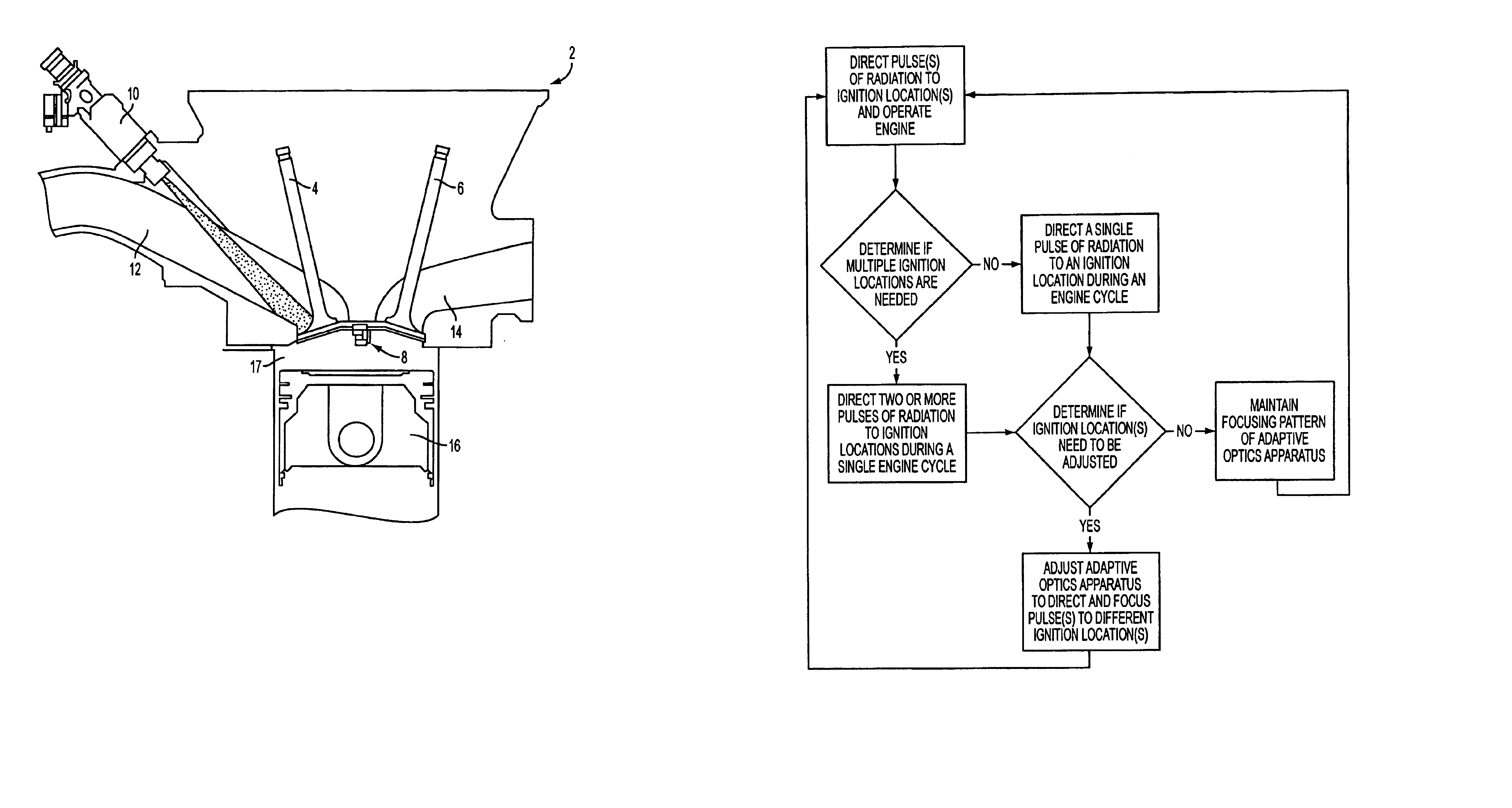
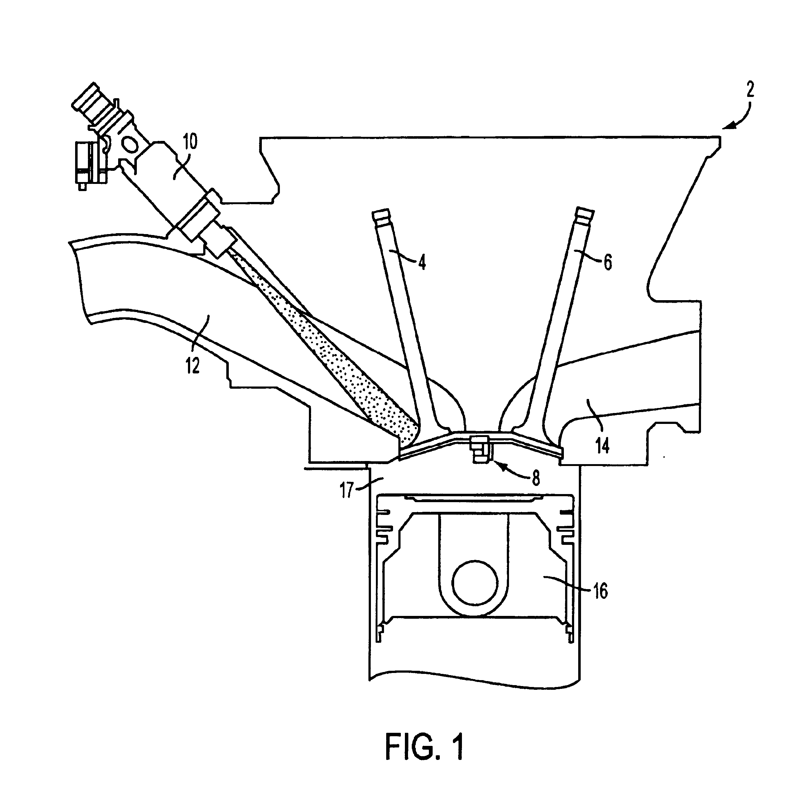
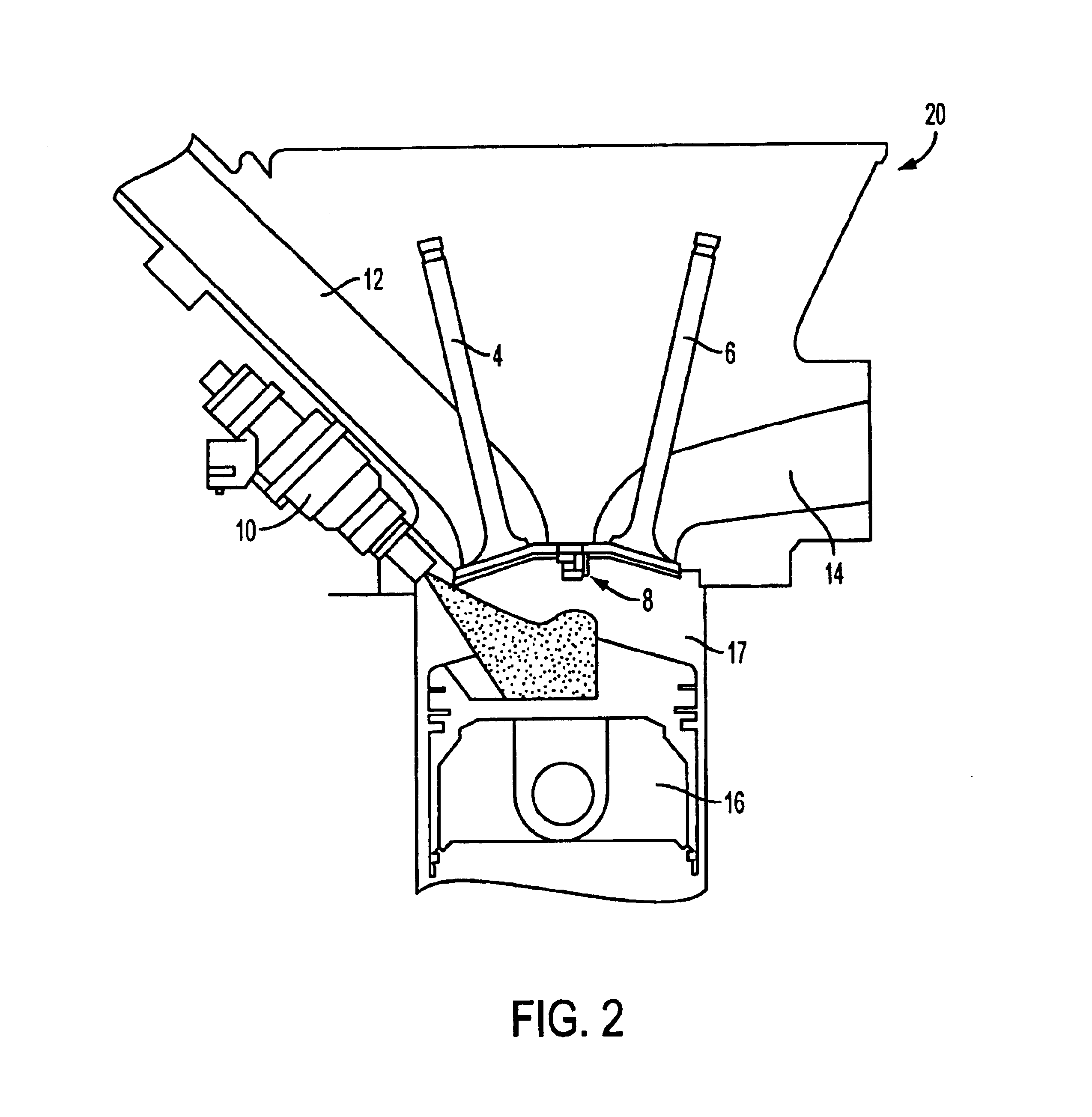
Turning to FIG. 4, there is shown a direct-injection engine 40 according to one embodiment of the present disclosure. It includes, among other components, the following: a high pressure fuel pump 41, an inlet port 42, a fuel injector 43, a combustion chamber 44, a laser 45, a beam steering mechanism 46, adaptive optics apparatus 47, a mounting block 48, an outlet port 49, a control unit 50, a piston 52, and a combustion chamber window 53. Several of these components may be commonly found in the field and do not warrant an exhaustive review herein. Included in that list are at least: the fuel pump, the inlet and outlet ports, the fuel injector, the piston, and the combustion chamber.

Before turning to a detailed description of individual component separately, it is worthwhile to first describe, in general terms, the operation of the engine illustrated in FIG. 4. One will note that the engine of FIG. 4 does not contain a spark plug. This absence is justified by the existence of the las...


PUM


Abstract

Methods and apparatuses for laser ignition in an internal combustion engine. Laser radiation is directed to an ignition location within a combustion chamber with adaptive optics, and the position of the ignition location is adaptively adjusted during operation of the engine using the adaptive optics. Multiple ignition locations may be provided during a cycle of an internal combustion engine. A first pulse of laser radiation is directed to a first ignition location within a combustion chamber with adaptive optics, and a second pulse of laser radiation is directed to a second ignition location within the combustion chamber using the adaptive optics.

Description

1. Field of the InventionThe present invention relates generally to the field of internal combustion engines. More particularly, it concerns methods and apparatuses for using laser ignition to adaptively adjust the position of one or more ignition locations within a combustion chamber during operation of an engine. It also concerns methods and apparatuses for providing multiple ignition locations during a single cycle of engine operation.2. Description of Related ArtIn a usual ignition apparatus for an internal combustion engine, a high voltage is applied to an ignition plug that is fixed on the wall surface of a combustion chamber in order to ignite an air-fuel mixture by spark discharge. In an ignition apparatus of this kind, however, several problems arise. For instance, since the ignition plug is exposed directly to the combustion chamber, carbon attaches to the ignition plug to render the discharge of the ignition plug difficult. Furthermore, due to a heat loss of the electrode...

Claims


Application Information

Patent Timeline
Patent Type & Authority Patents(United States)
IPC IPC(8): F02B23/10F02P23/00F02P23/04F02B23/08F02D19/02F02D45/00F02M21/02F02P5/152F02P5/153
CPCF02B23/104F02P15/08F02P23/04Y02T10/125Y02T10/12
Inventor RYAN, III, THOMAS W.
Owner III HLDG 1
Why Eureka
Try Eureka