Routing optical matrix switching method and device

a switching method and optical matrix technology, applied in multiplex communication, instruments, optical elements, etc., can solve the problems of large insertion loss, difficult and complex to perform m.times.n all-optical cross-connection, etc., and achieve low insertion loss, low polarization dependent loss, and low cross-talk

Inactive Publication Date: 2004-09-28
HUAZHONG UNIV OF SCI & TECH
View PDF7 Cites 9 Cited by
  • Summary
  • Abstract
  • Description
  • Claims
  • Application Information

AI Technical Summary

Benefits of technology

The purpose of the present invention is to provide a simple and flexible M.times.N optical matrix switching method and device, where M=2.sup.m, M=0,1,2 . . . ; N=2.sup.n, n=0,1,2 . . . , to greatly reduce the insertion loss of signal beam between input fiber and output fiber and to increase its switching rate. To realize the object, the present invention puts forward a routing optical matrix switching method and device, thereof.
In the routing parallel optical channel unit and routing combination unit of parallel optical channel of the above-mentioned optical matrix switching device, said optical switching array can be an optical switching of movable wavelength plate array, or a liquid-crystal optical switching device as well. The crystal prism can be a trapezoid polarization prism as well as a birefringence crystal prism. In comparison with a bidirection optical matrix-switching device, an unidirection optical matrix-switching device is simple, moreover, both the last stage of optical switching array and the parallel plane crystal units. can be left out in routing combination unit of parallel optical channels.
The M.times.N optical matrix switching method and device of the present invention have the following various advantages: low insertion loss, low polarization dependent loss, low cross-talk, simplified, flexible, and scalable. The M.times.N optical matrix switching device can widely be used for varieties of all-optical cross connection, optical add / drop OADM and optical wavelength route OXC equipment in the field of WDM optical communication.

Problems solved by technology

It is difficult and complex to perform M.times.N all-optical cross-connection, although easily achieving 1.times.N or 2.times.N all-optical cross connection.
The M.times.N all-optical cross-connection with the method of conventional optical Crossbar switching network must cause very large insertion loss in the processes of 1.times.N fan-out and M.times.1 fan-in.

Method used


Image

  • Routing optical matrix switching method and device
  • Routing optical matrix switching method and device
  • Routing optical matrix switching method and device

Examples


Embodiment Construction

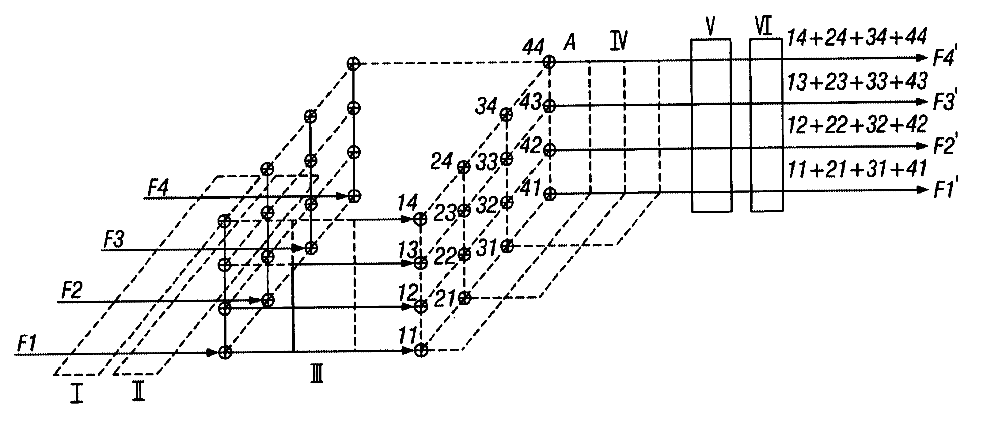
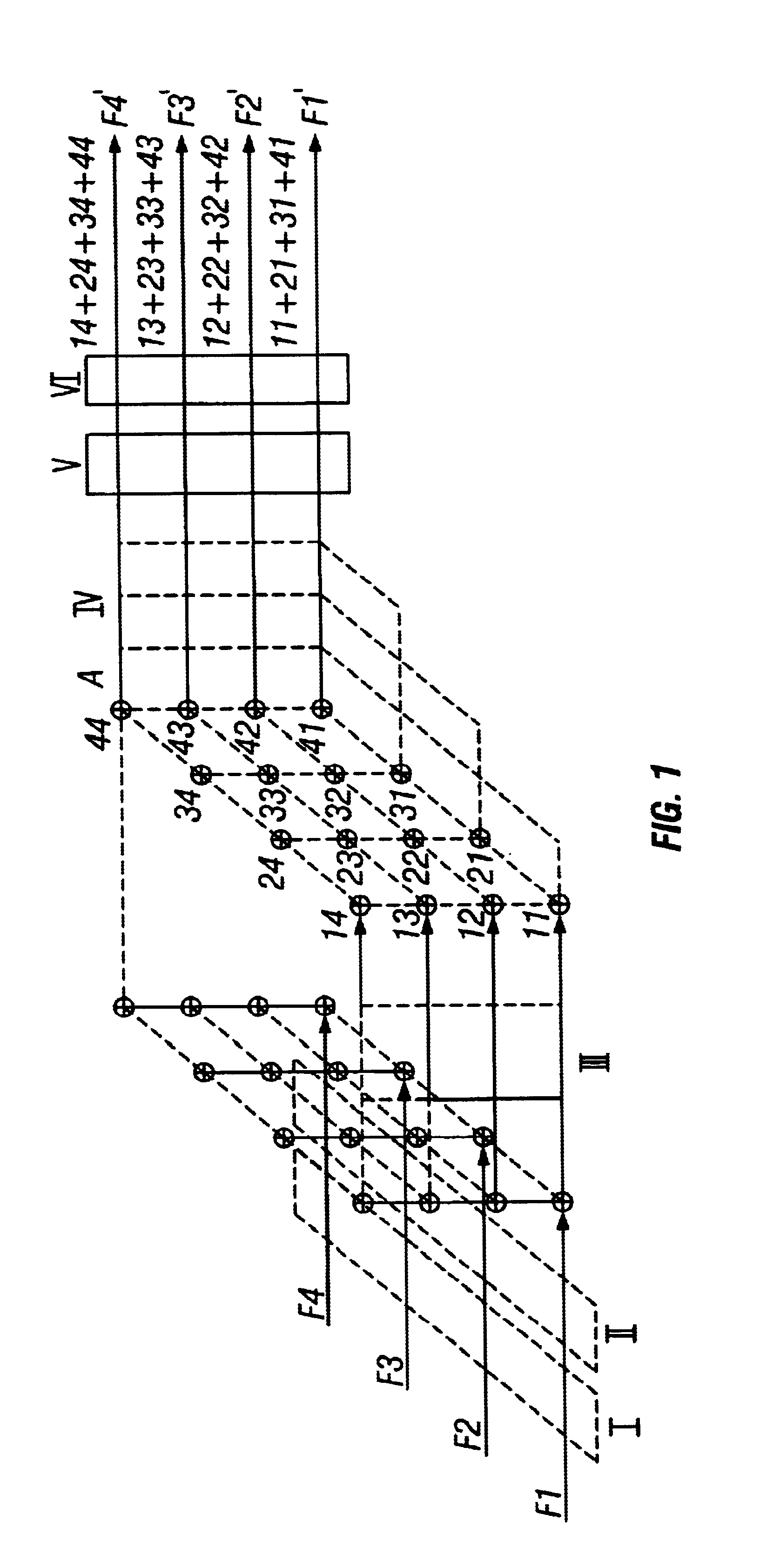
A 4.times.4 optical matrix switch, as one embodiment of the present invention, will be described hereinafter with reference to the drawings.

In FIG. 1, four divergent signal beams F1, F2, F3, F4 are converted into collimated parallel light beams via an optical collimated unit of one dimension fiber array I. And then become linear polarization light beams through parallel plane crystal unit II, and further each signal beam is provided with four parallel optical channels in the y direction after passing through routing parallel optical channel unit III. Thus, there are totally 4.times.4 parallel output optical channels available for four input signal beams. In the routing combination unit of parallel optical channel, having passed through a .lambda. / 2 is wavelength plate array A and a routing combination unit of parallel optical channel IV, four parallel output optical channels in the x direction are, routing combined into one optical channel, such as a routing combination 13+23+33+43;...


PUM

PropertyMeasurementUnit
angleaaaaaaaaaa
sizeaaaaaaaaaa
outer diameteraaaaaaaaaa

Abstract

The switching method is constituted with a novel nonblocking routing optical crossbar network system. It includes two parts: one is a routing fan-out unit which provides N parallel optical channels for each of M input light beams, and the other is a routing combination unit in which M parallel optical channels that have the same output port, are routing combined into one optical parallel channel of N parallel output channels by the routing fan-in network. According to the method of the present invention, the optical module of MxN (M=2<m>, N=2<n>, m and n are nature numbers) routing matrix switching can be developed.

Description

The present invention relates to a routing optical matrix switching method and a device for an optical communication. More specifically, the present invention relates to a routing optical matrix switching method and a device for WDM. optical communication networks.Recently, all developed countries in the world are preparing to establish WDM high-speed fiber communication networks. So those countries need a great number of all-optical cross connections and fiber protection switch-equipment, optical adding / dropping multiplex OADM and optical wavelength route OXC equipment and the like, of which the most vital device is optical matrix switching device. However, optical matrix switching devices available on the market are switched between input fibers and output fibers with high precision machine-driving fiber or driving optical prism, referring to the product catalogs of The USA Dicon fiber Optics Inc, E-TEK Inc and Canada JDS, and also seeing "Optical Components for WDM Lightwave Netw...

Claims


Application Information

Patent Timeline
Patent Type & Authority Patents(United States)
IPC IPC(8): G02F1/31G02B6/34G02B6/35G02F1/29H04Q11/00G02F1/13G02F1/141
CPCG02B6/29302G02B6/29395G02B6/3542G02B6/356G02F1/31H04Q11/0005G02B6/3522G02B6/3546G02B6/3548G02B6/3582G02B6/3594G02F1/141G02F2001/311H04Q2011/0024H04Q2011/0035H04Q2011/0058H04Q2011/0073G02F1/311
Inventor CAO, MINGCUI
Owner HUAZHONG UNIV OF SCI & TECH
Why Eureka
Try Eureka