
Calibration of a loss of signal detection system

a signal detection and signal technology, applied in the field of integrated circuits used in communication systems, can solve problems such as difficult implementation of cmos technologies, data transmission interruptions, and loss of signal techniques

Inactive Publication Date: 2004-09-28
SILICON LAB INC
View PDF5 Cites 19 Cited by
  • Summary
  • Abstract
  • Description
  • Claims
  • Application Information

AI Technical Summary

Benefits of technology

During calibration, the digital control block 111 stores a digital representation corresponding to the value of the LOS threshold level. The digital control block 111 uses the stored digital value corresponding to the LOS threshold level to set the level at which the high-speed register 115 latches a one or a zero, using the LOS threshold signal conveyed on node 127. The digital control block 111 also monitors the decimated count from the decimator in order to determine when to assert the LOS indication 125 (LOS_OUT). Since the digital control block operates at a rate significantly slower than the input data rate and slower than high-speed register 115 (e.g., in one embodiment no input or output of the digital control block operates at a rate faster than 155 MHz), the power used by the digital control block is reduced and the use of digital synthesis and place-and-route tools to generate the digital control block is facilitated, which simplifies the design. Note that the clock rates described herein are exemplary and that different clock rates may be suitable for different systems.

Problems solved by technology

Interruptions occur in data transmission for a variety of reasons such as equipment failure, a cut cable or excessive attenuation of the signal.
However, such loss of signal techniques has been typically implemented in bipolar technologies.
Their implementation in CMOS technologies is difficult.

Method used


Image

  • Calibration of a loss of signal detection system
  • Calibration of a loss of signal detection system
  • Calibration of a loss of signal detection system

Examples


Embodiment Construction

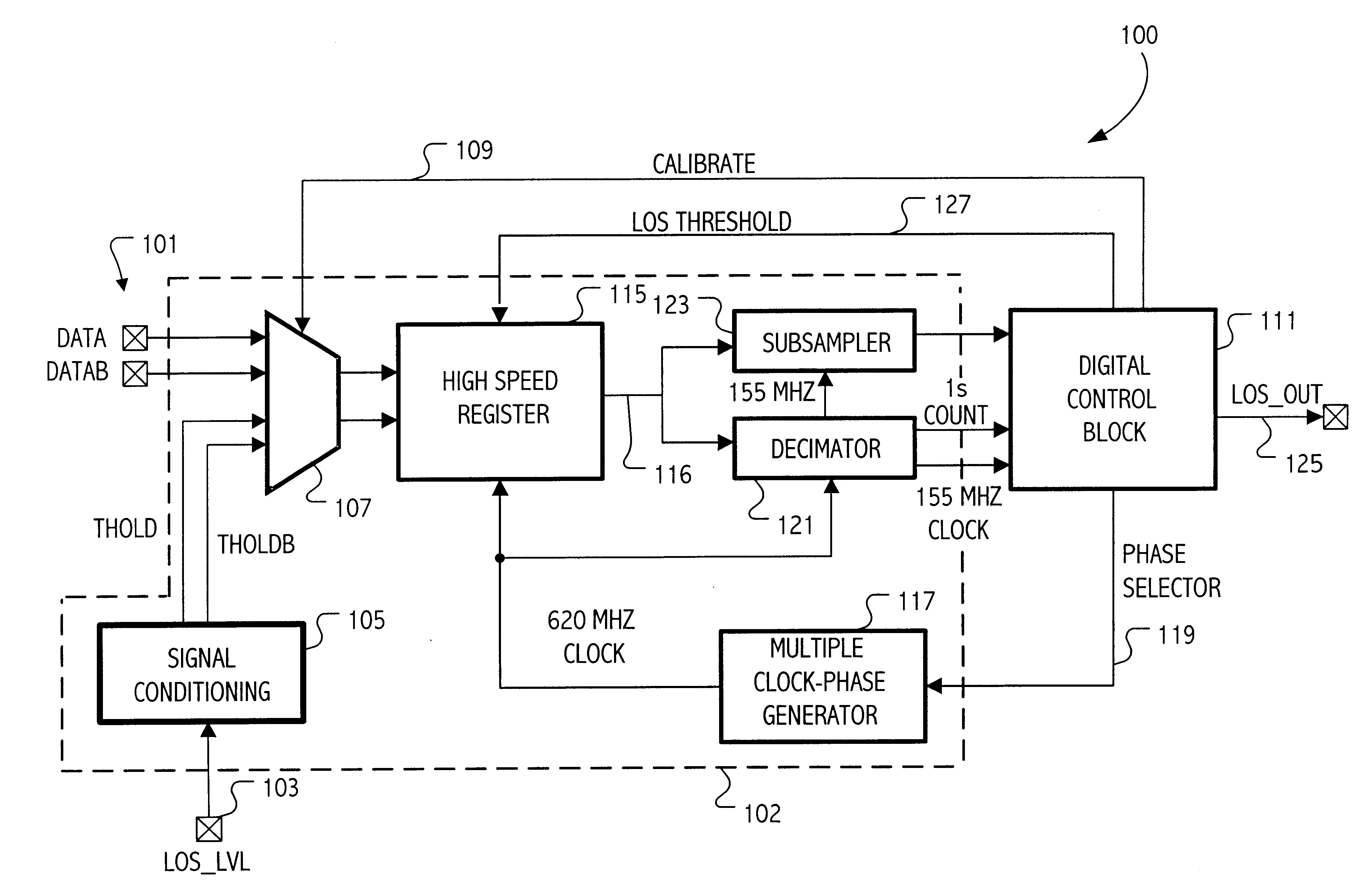
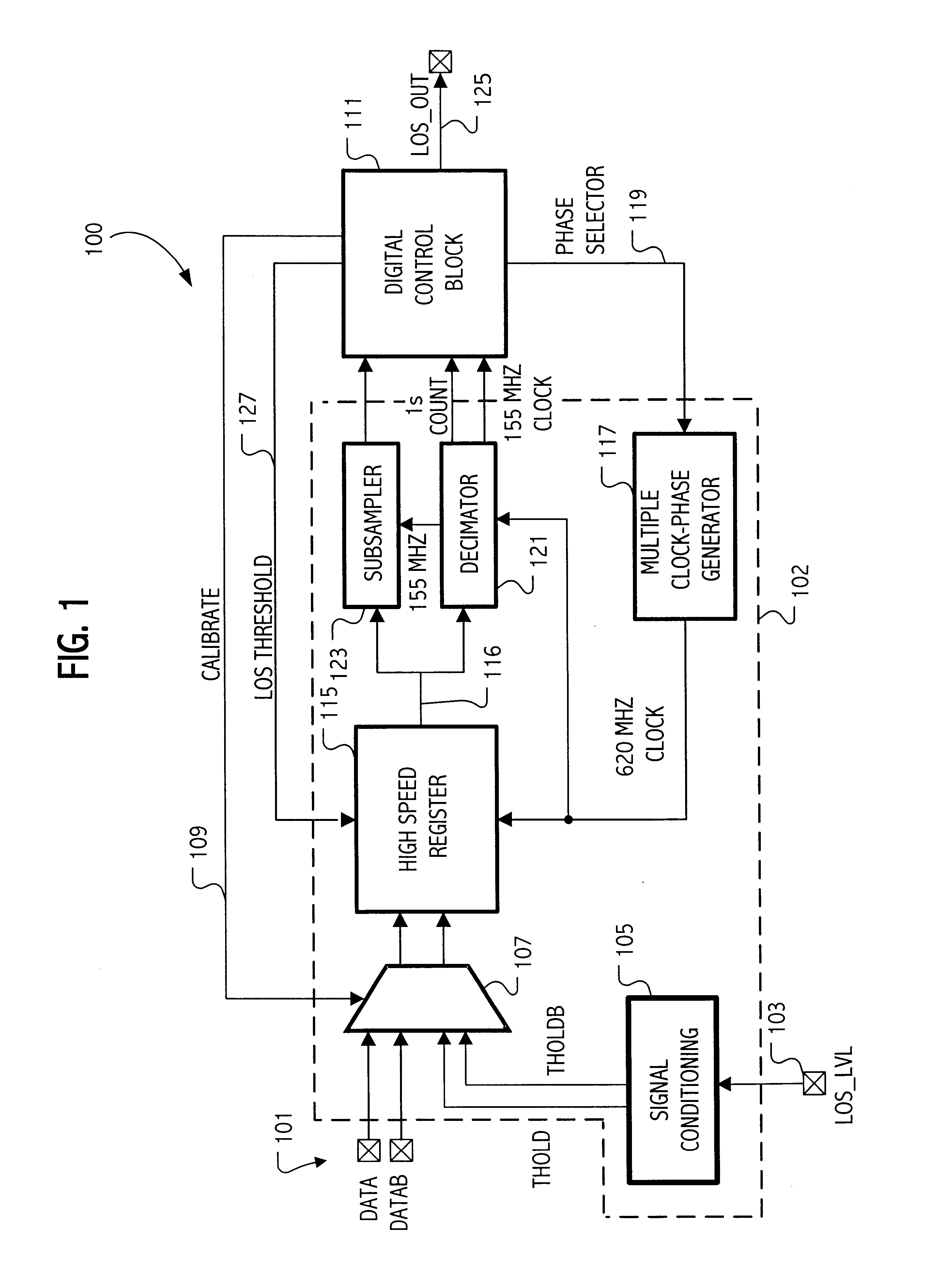
FIG. 1 shows a block diagram of one embodiment of the LOS system 100 according to the present invention. The loss-of-signal (LOS) system utilizes a sampled-data approach, which samples the input data at regular intervals and compares the magnitude of the sampled input data to a threshold signal strength level. If the number of samples that have a signal strength above the signal strength threshold exceeds a count threshold, then a LOS indication is not asserted. However, if the number of samples with signal strength greater than the threshold is less than the count threshold, then the LOS indication is asserted, thereby indicating that the LOS condition exists.

The input data 101 comes into the system differentially. The voltage on the LOS_LVL input terminal 103 determines the user-defined LOS threshold level. In another embodiment, the threshold may be fixed or may be provided via, e.g., a serial communication port.

The signal conditioning block 105 converts this single-ended input i...


PUM


Abstract

An integrated circuit has a loss of signal (LOS) system for detecting a loss of signal condition for an input data stream according to a LOS threshold. The LOS threshold specifies a minimum signal magnitude indicating the loss of signal condition. The integrated circuit includes a sampling circuit to sample a LOS signal, which receives a sampling threshold specifying a signal magnitude for a sampled signal above which the sampling circuit samples the sampled signal as a first digital value and below which the sampling circuit samples the sampled signal as a second digital value. A digital control circuit coupled to an output of the sampling circuit generates a calibrated digital representation of the sampling threshold according to a plurality of samples of the LOS signal. The calibrated sampling threshold is then used during loss of signal evaluation.

Description

1. Field of the InventionThis invention relates to integrated circuits used in communication systems and more particularly to detection of loss of signal conditions associated therewith.2. Description of the Related ArtInterruptions occur in data transmission for a variety of reasons such as equipment failure, a cut cable or excessive attenuation of the signal. When such an interruption occurs, it is typical for the intended receiver in the data transmission system to detect the failure condition and inform the communication system of the existence of the failure. Many communication systems specify various aspects of detecting such loss of signal (LOS) conditions. For example, the Synchronous Optical Network (SONET) specification requires that LOS be raised when the synchronous signal (STS-N) level drops below the threshold at which a bit error rate (BER) of 1.times.10.sup.-3 is predicted.A clock and data recovery circuit operating in such a communication system typically receives t...

Claims


Application Information

Patent Timeline
IPC IPC(8): H03K5/22H03K5/19
CPCH03K5/19
Inventor STEINER, PHILIP DAVIDPERROTT, MICHAEL H.
Owner SILICON LAB INC
Learn More