Method for determining the optimum observer heading change in bearings-only passive emitter tracking

a passive emitter and bearing technology, applied in direction finders, instruments, communication jamming, etc., can solve the problems of inconvenient convergence, large risk, intrinsically less accurate passive emitter tracking or ranging, etc., and achieve the effect of improving performan

Inactive Publication Date: 2004-10-05
NORTHROP GRUMMAN SYST CORP
View PDF13 Cites 24 Cited by
  • Summary
  • Abstract
  • Description
  • Claims
  • Application Information

AI Technical Summary

Benefits of technology

It is thus an object of the present invention to combine TMA, which requires multiple data collection legs, and the single-leg track estimation approach described in inventor's co-pending application, in a manner overcoming the deficiencies in both and improving the performance of each.

Problems solved by technology

However, passive emitter tracking or ranging is intrinsically less accurate than active radar tracking and requires many bearing measurements, and hence, additional time to converge to a solution.
The fact that the observer does not know the emitter's location or velocity until after the observer has maneuvered introduces a large element of risk when aircraft use TMA for target tracking.
As McCabe noted, conventional TMA implementations, such as that described by Aidala, are unable to take advantage of the above facts.
This has potentially dire tactical consequences when the observer is a high-speed aircraft , such as an air-intercept (AI) jet, engaging a high speed threat.
Not only can McCabe's results not be exploited, but if the Al aircraft is initially leading the target, inadvertently performing a suboptimal lead-lead maneuver may put the aircraft in a vulnerable position.
But executing the optimal lead-lag maneuver, i.e. turning away on the second leg, may cause the aircraft to fail to intercept the target.
But, the simple data base and logic mean there will be many more speed ambiguities, and, even for one discrete speed, significant uncertainty about its correct value.
Thus, while a complex implementation can achieve accuracies for many emitters of 5%, a simple implementation has errors typically at least three times greater than the complex implementation.

Method used


Image

  • Method for determining the optimum observer heading change in bearings-only passive emitter tracking
  • Method for determining the optimum observer heading change in bearings-only passive emitter tracking
  • Method for determining the optimum observer heading change in bearings-only passive emitter tracking

Examples


Embodiment Construction

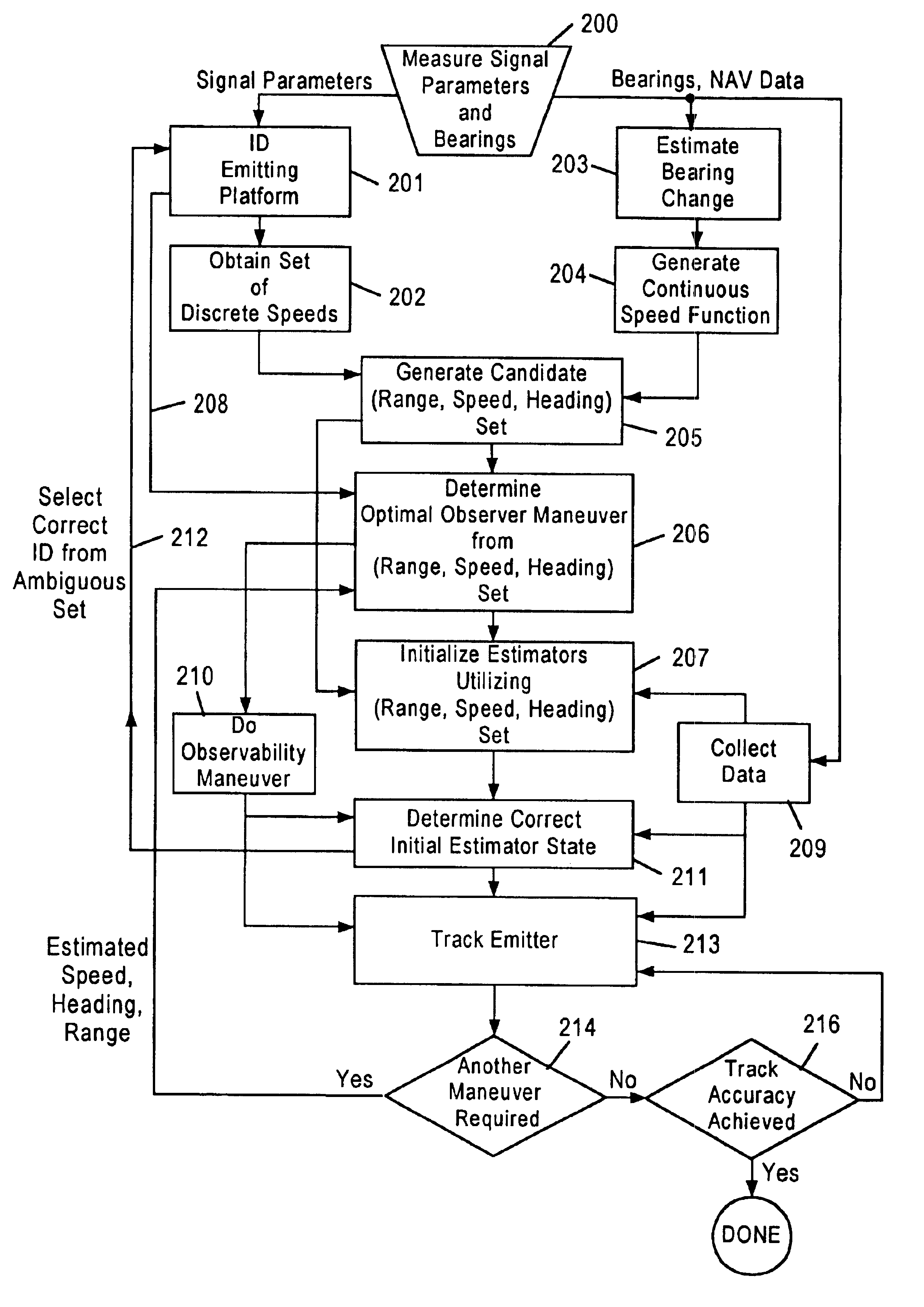
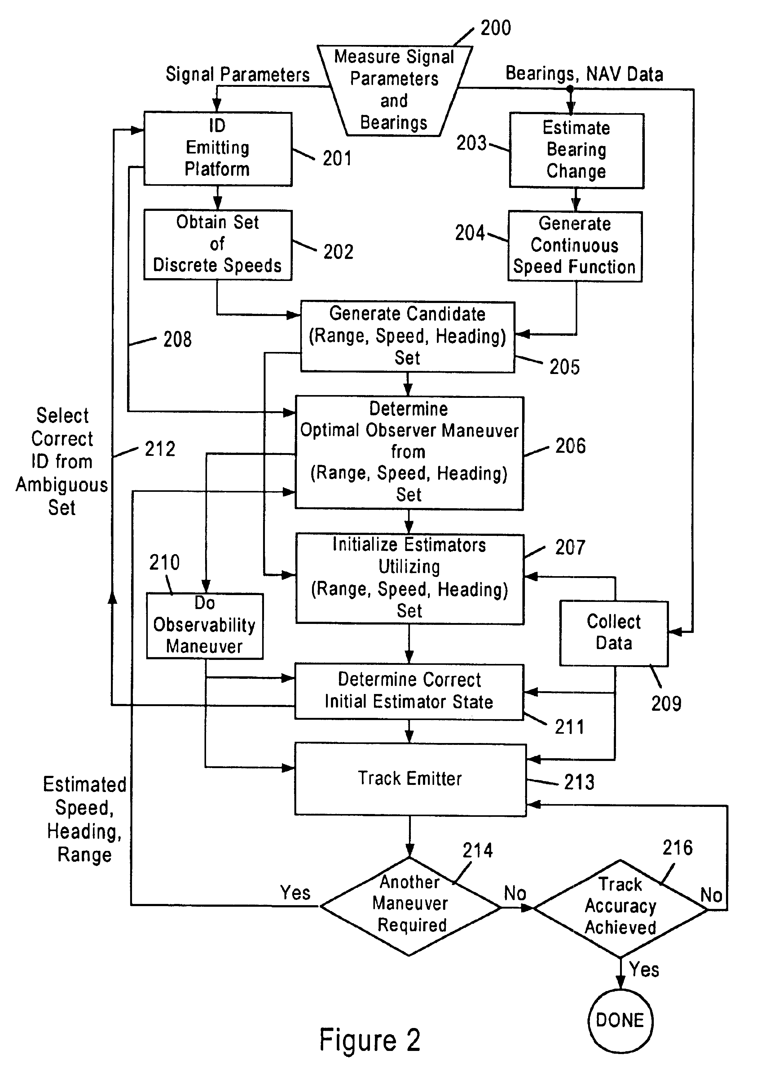
A logic flow chart of an embodiment of the present invention is depicted in FIG. 2. Process steps 200 through 205 occur prior to the observability maneuver in step 210.

Steps 200-205 are similar to the steps described in the inventor's copending application with a key difference. Unlike the aforementioned disclosure, the signal parameters extracted in step 200 are not required to uniquely or nearly uniquely identify the platform type in step 201. Hence, a large set of speeds may be obtained in step 202. Typically, the set may contain over twenty discrete speeds. Process steps 203 and 204 estimate speed as a function of unknown range and heading. These steps may be implemented as described in the aforementioned disclosure. Comparing this single continuous speed with each discrete speed from step 201 generates (step 205) a set of range and velocities consistent with each discrete speed.

As part of the ID emitting platform process (Step 201), an error for the discrete speed estimate is d...


PUM


Abstract

Emitter target range and heading are estimated from bearing measurements enhancing bearings-only estimator convergence to a target track, and permitting optimization of an observer position relative to the target at the end of the total bearing measurement period. One or more estimates of the target range, speed and heading made from bearing measurements before an observer maneuver are used to determine the most appropriate observer maneuver giving complete bearings-only target-motion-analysis observability. A set of parameters characterizing a set of potential emitter signal sources is generated based on measured emitter characteristics. A most probable set of emitter platforms is identified and the emitter operating mode and corresponding platform set are associated with a kinematic regime set. A specific speed or discrete set of speeds best adapted to a set of all possible platform missions, emitter speed as a continuous function of emitter range, and emitter range are all determined.

Description

The present invention relates generally to radars, and more particularly, to bearings-only passive emitter tracking. Even more particularly, the present invention is related to a method of and apparatus for determining the optimum observer heading change in bearings-only passive emitter tracking.A moving observer, e.g. an aircraft, able to measure bearings to an emitter, generates the range, speed and heading of the emitter based on the measured bearings. This bearings-only passive emitter tracking is called target motion analysis (TMA). Passive TMA is useful because emitters can be detected and tracked at much longer ranges than possible using active radar.However, passive emitter tracking or ranging is intrinsically less accurate than active radar tracking and requires many bearing measurements, and hence, additional time to converge to a solution. Also bearings-only TMA requires the observer to maneuver at some point during the bearing measurement period. The fact that the observ...

Claims


Application Information

Patent Timeline
Patent Type & Authority Patents(United States)
IPC IPC(8): G01S11/00G01S11/04G01S11/02G01S19/48
CPCG01S11/04G01S11/026
Inventor ROSE, CONRAD
Owner NORTHROP GRUMMAN SYST CORP
Why Eureka
Try Eureka