

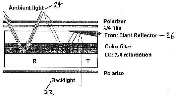
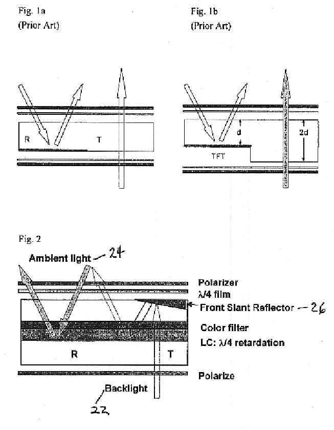
Single cell gap transflective liquid crystal display with slanted reflector above transmissive pixels
a liquid crystal display and reflector technology, applied in static indicating devices, instruments, non-linear optics, etc., can solve the problems of low contrast ratio, inferior color saturation to those of transmission types, and high power consumption, and achieve the effect of reducing the number of pixels in the transmission type, and improving the color saturation of the transmission typ
- Summary
- Abstract
- Description
- Claims
- Application Information
AI Technical Summary
Benefits of technology
Problems solved by technology
Method used
Image

Examples
example 1
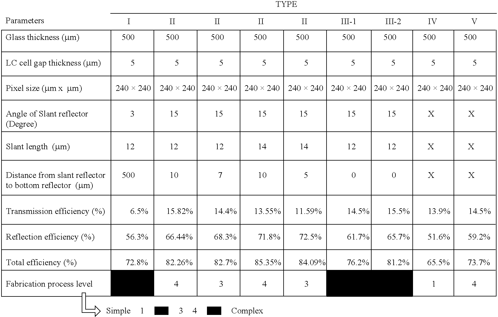
The dimensions of the slant reflector on the front surface of top glass and the simulation parameters are listed in Table 1.
The simulation calculates the light efficiency of reflection and transmission with different illumination angles. As shown in FIG. 11, the highest reflection light efficiency is approximately 81% at normal incident (.theta.=0.degree., .phi.=0.degree.), and the lowest is approximately 48.36% at azimuthal angle (.phi.) equals approximately 45.degree. and polar angle (.theta.) larger than .+-.5.degree.. In addition, the transmission light efficiency reaches approximately 17.62% for the normal incident backlight and is decreased to approximately 1.4% at (.theta.=.+-.6.degree., .phi.=45.degree.). The half efficiency angle range of reflection and transmission is approximately 3.degree. and approximately 2.5.degree., separately.
example 2
The slant reflector on the backside of top glass and the simulation parameters are shown hereafter in Table. 2. The distance between slant reflector to and the reflector at the bottom of liquid crystal layer is approximately 25 .mu.m.
The simulation calculates the light efficiency of reflection and transmission with different illumination angles. As shown in FIG. 12 the highest reflection light efficiency is approximately 81% at normal incident (.theta.=0.degree., .phi.=0.degree.), and the lowest is approximately 48.36% at azimuthal angle (.phi.) equals 45.degree. and polar angle (.theta.) larger than approximately .+-.35.degree.. In addition, the transmission light efficiency is approximately 17.62% for the normal incident backlight and is decreased to approximately 2.45% at (.theta.=approximately .+-.30.degree., .phi.=approximately 45.degree.). The half efficiency angle range of reflection and transmission is approximately 30.degree. and approximately 25.degree., separately.
example 3
The slant reflector on the backside of top glass with various distance (D) between slant reflector and the reflector at the bottom of liquid crystal layer had been simulated. The parameters are the same as shown in Table 2. The average light efficiency of reflection and transmission had been calculated. The ambient light was assumed as illuminated from polar angle .theta.=0.degree. to .theta.=45.degree. and azimuthal angle .phi.=+45.degree. to .phi.=-45.degree.. The backlight was assumed as .+-.20.degree. divergent angle. The simulated average efficiency is shown in Table 3.
PUM
| Property | Measurement | Unit |
|---|---|---|
| light transmittance | aaaaa | aaaaa |
| length | aaaaa | aaaaa |
| length | aaaaa | aaaaa |
Abstract
Description
Claims
Application Information