Write clock and data window tuning based on rank select

a clock and data window technology, applied in the field of memory subsystems, can solve the problems of slowing the processing speed of the entire system, synchronous systems, and difficult data integrity maintenance,

Inactive Publication Date: 2004-10-12
MICRON TECH INC
View PDF6 Cites 213 Cited by
  • Summary
  • Abstract
  • Description
  • Claims
  • Application Information

AI Technical Summary

Problems solved by technology

Disadvantageously, this wait state slows the processing speed of the entire system.
Synchronous systems, however, do offer additional design challenges.
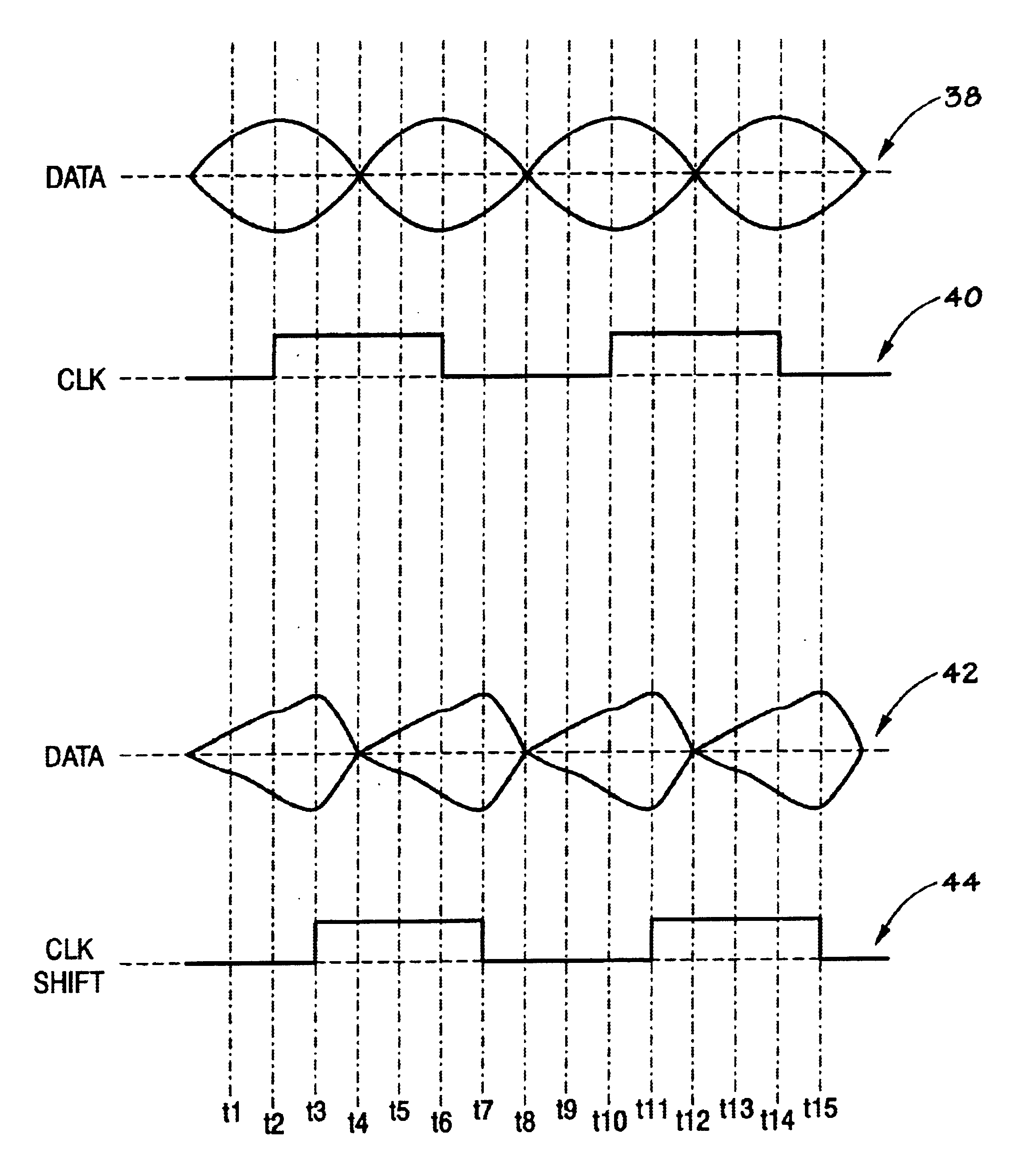
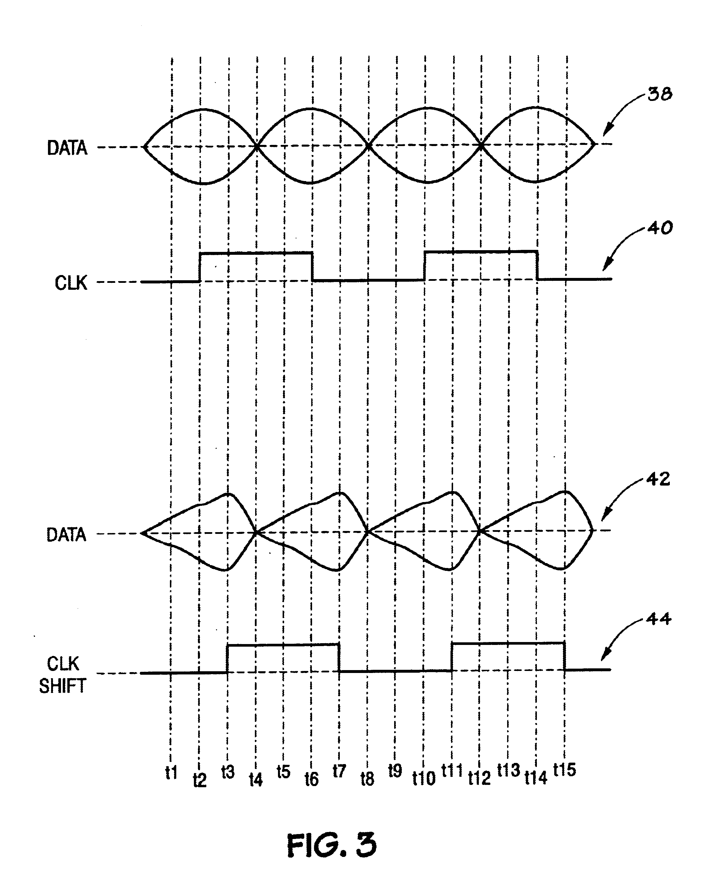
One such challenge is maintaining optimal alignment of a data or command signal with respect to the clock signal.
Data integrity is difficult to maintain and varies depending on the physical location of the slot as well as the loading at various points in the memory sub-system.
Because a request signal may look different at various locations along the bus, it is difficult to align the clock signal such that it is optimized for requests going to the various slots along the memory bus.
What is optimal for a memory module at a first location may not be optimal for a memory module at a second physical location along the bus since the data eye may be shifted, skewed, or degraded.

Method used


Image

  • Write clock and data window tuning based on rank select
  • Write clock and data window tuning based on rank select
  • Write clock and data window tuning based on rank select

Examples


Embodiment Construction

One or more specific embodiments of the present invention will be described below.

In an effort to provide a concise description of these embodiments, not all features of an actual implementation are described in the specification. It should be appreciated that in the development of any such actual implementation, as in any engineering or design project, numerous implementation-specific decisions must be made to achieve the developers' specific goals, such as compliance with system-related and business-related constraints, which may vary from one implementation to another. Moreover, it should be appreciated that such a development effort might be complex and time consuming, but would nevertheless be a routine undertaking of design, fabrication, and manufacture for those of ordinary skill having the benefit of this disclosure.

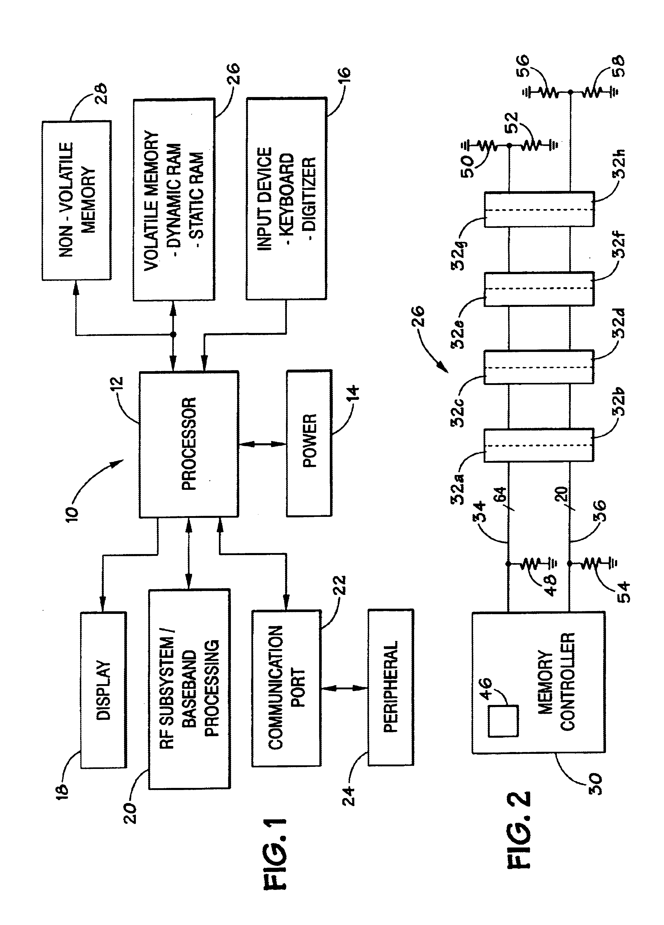
Turning now to the drawings, and referring initially to FIG. 1, a block diagram depicting an exemplary processor-based system, generally designated by reference ...


PUM


Abstract

A configuration register used to adjust a clock or request signal with respect to the other. Specifically, a look-up table is provided in the memory controller. The look-up table is filled at bootup such that it contains test information from a master look-up table in the system BIOS, for instance. The look-up table in the memory controller stores current test data correlative to optimal sampling times for the current configuration. Adjustable delay elements or adjustable load elements may be used to change the relative sampling time of the request signal correlative to the values stored in the memory controller look-up table.

Description

1. Field of the InventionThe present invention relates generally to memory sub-systems, and more specifically to a technique for tuning signals based on the physical location of the signal destination.2. Description of the Related ArtThis section is intended to introduce the reader to various aspects of art that may be related to various aspects of the present invention, which are described and / or claimed below. This discussion is believed to be helpful in providing the reader with background information to facilitate a better understanding of the various aspects of the present invention. Accordingly, it should be understood that these statements are to be read in this light, and not as admissions of prior art.In today's high speed computer systems, requests are initiated to the memory sub-system in rapid succession. Historically, memory devices in the memory sub-system have been controlled asynchronously by the processor. In asynchronous systems, the processor strobes the requested...

Claims


Application Information

Patent Timeline
Patent Type & Authority Patents(United States)
IPC IPC(8): G06F13/16G06F13/42
CPCG06F13/4243G06F13/1694
Inventor LABERGE, PAUL A.DODD, JIM
Owner MICRON TECH INC
Why Eureka
Try Eureka