Apparatus and method for reducing implant angle variations across a large wafer for a batch disk

a batch disk and ion implantation technology, applied in electrical equipment, nuclear engineering, electric discharge tubes, etc., can solve the problems of batch type ion batch type implanter angle integrity degradation, etc., to minimize the rotation error of the pad, minimize the tilt/twist angle variation, and minimize the effect of rotation error

Inactive Publication Date: 2004-10-19
ADVANCED ION BEAM TECHNOLOGY INC
View PDF1 Cites 17 Cited by
  • Summary
  • Abstract
  • Description
  • Claims
  • Application Information

AI Technical Summary

Benefits of technology

It is the object of the present invention to provide a new system configuration and method for carrying out batch type ion implantations. The present invention discloses methods and special disk / pad configurations for a batch type implanter to apply large angle implant. The new disk / pad arrangements provide mechanism to rotate each pad to a large angle and lock it in place firmly against the large centrifugal torque trying to rotate the pad back to zero tilt angle, to minimize pad rotation error. Furthermore, this invention provides a method to concave into a wafer surface to follow a concaved pad surface similar to the wafer natural bending shape, with maximum deformation the same as the desired conical pad surface which gives minimal tilt / twist angle variation, to minimize tilt / twist angle variation during disk spinning and at the same time maximize thermal contact between the wafers and the concaved pad surfaces.

Problems solved by technology

Conventional technology of batch type ion implanter is still limited by the technical difficulties of degraded angle integrity due to significant angle variations across the surface of a wafer in carrying out a large angle implantation.
Particularly, the difficulties exist in the batch type implanters wherein a rotating disk is implemented to carry multiple wafers, i.e. a batch of wafers.
However, the ion implanters as disclosed by Mack still have the limitation that the cylindrical surface of the wafer cannot resolve the difficulty of angle implant while maintaining sufficient wafer cooling during implantation.
It is impossible in reality for a batch disk to rotate at the high speed due to mechanical limitation, such as disk balance, disk material strength, and wafer damage by clamp mechanism.
If a wafer cannot deform onto the cylindrical pad surface, its thermal contact with the water-cooled pad surface would be very weak and wafer cooling would not be sufficient.
The problems of angle variations across a large wafer surface are particularly pronounced when the semiconductor industry moves toward sub-micron node technology and the large angle implantation becomes a requirement for high dosage implantations.
The conventional batch type disk cannot provide large angle implant due to large disk dimension in a narrow disk chamber.
Furthermore, the beam-to-wafer distance varies at different tilt angle that makes it hard to control beam size at the wafer thus the beam current performance will be greatly reduced at low energy due to beam blow-up.
Similar to Mack's invention, this implanter also has a limitation and difficult that there is a poor contact between the wafers and the conical pad surfaces at practical spin speed of <1000 rpm.
The heat dissipation of the wafers can be a limitation for the implanter utilizing conically shaped wafer pad surface as that disclosed by Takeyama.
However, the methods and apparatuses as disclosed by Aitken require the individual pad rotation control to vary the implant angle, thus introduces many technical difficulties that have not been resolved by the conventional implanters.

Method used


Image

  • Apparatus and method for reducing implant angle variations across a large wafer for a batch disk
  • Apparatus and method for reducing implant angle variations across a large wafer for a batch disk
  • Apparatus and method for reducing implant angle variations across a large wafer for a batch disk

Examples


second embodiment

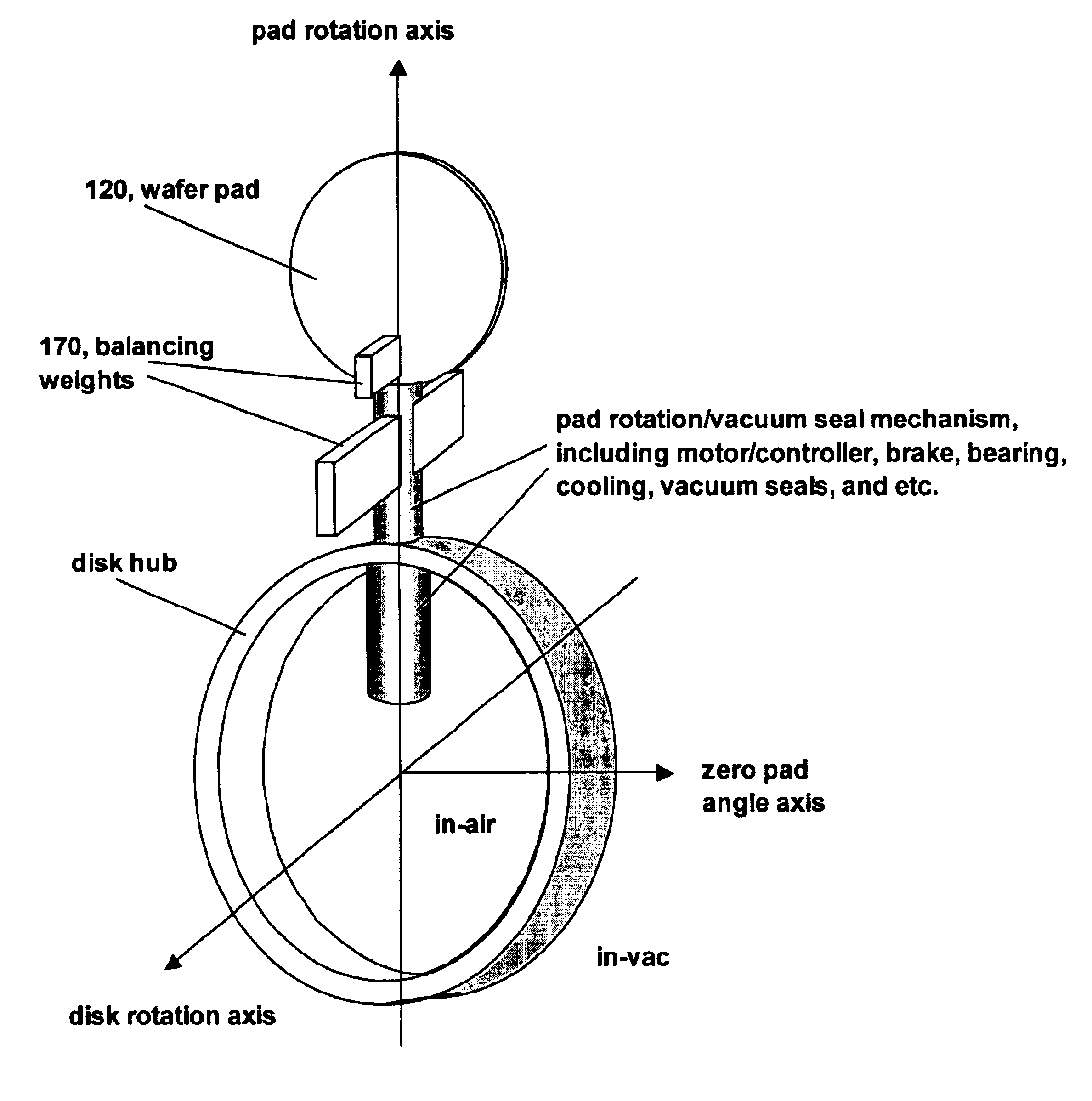
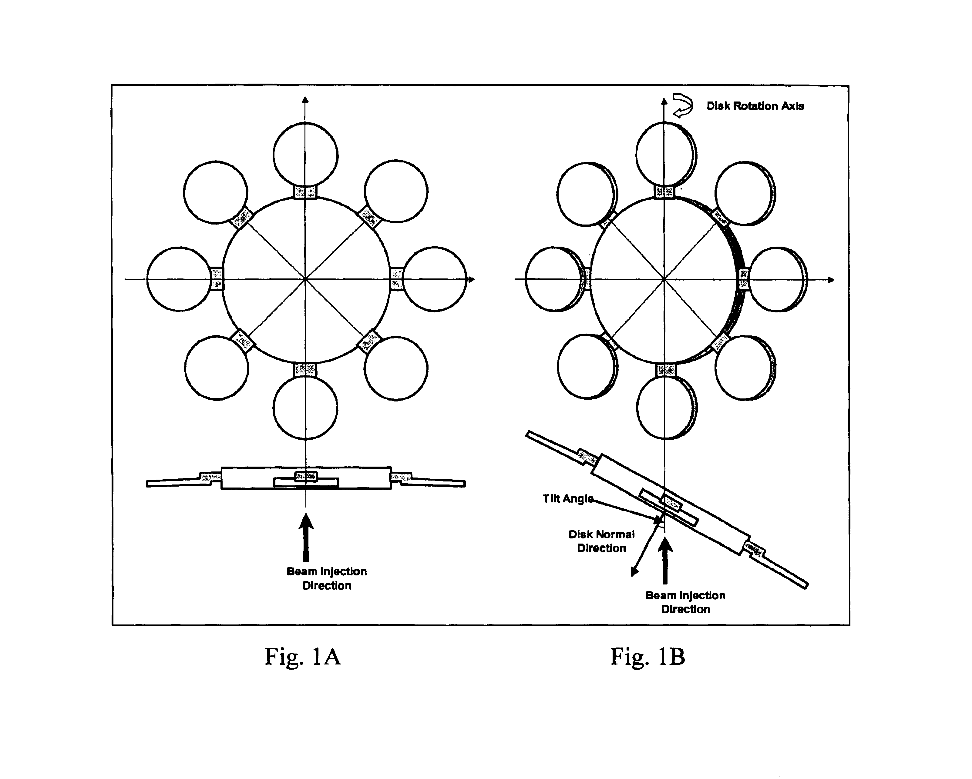
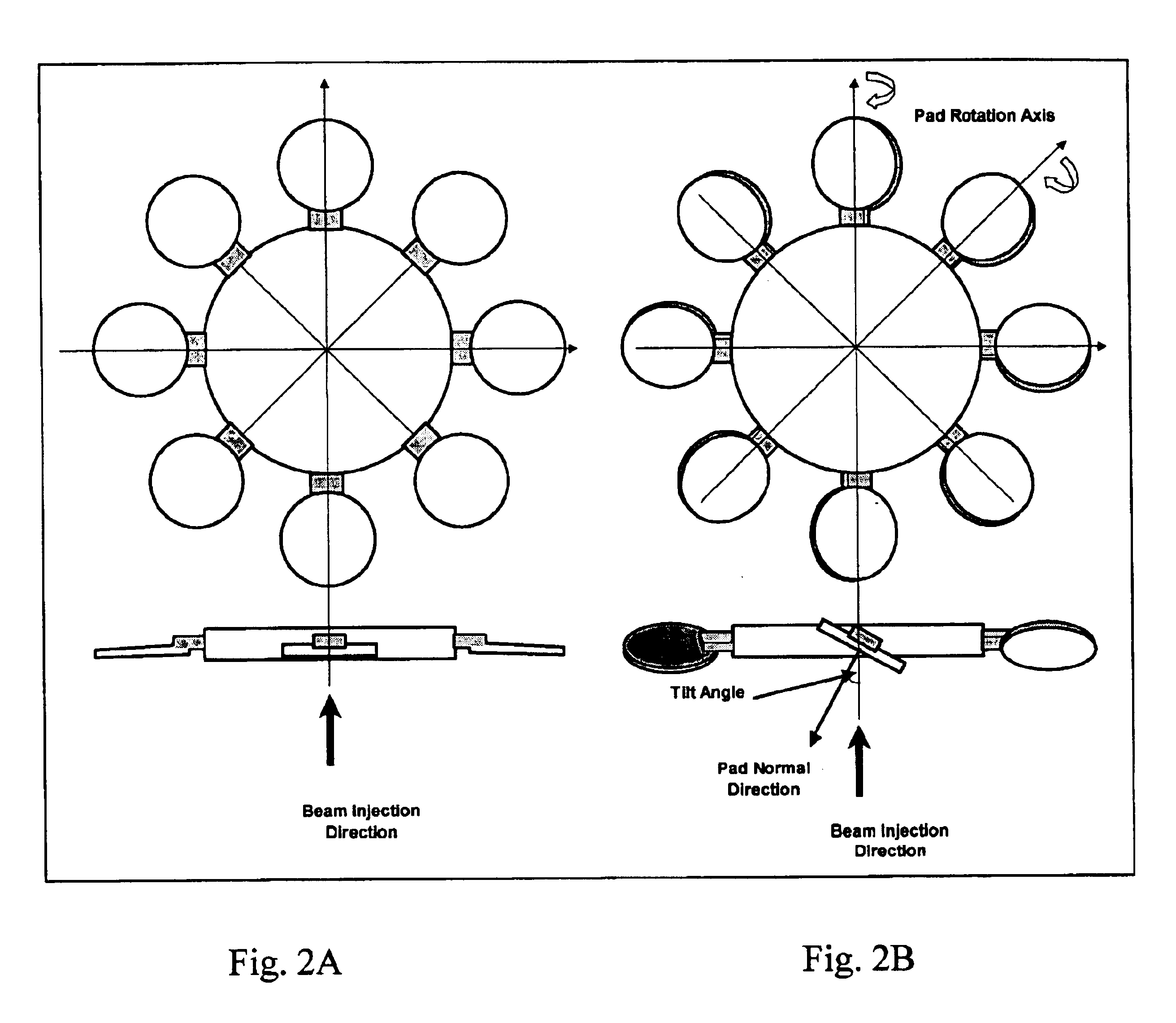
The first embodiment of present invention is to individually rotate each substrate pad of a batch disk to allow implant angle control. The second embodiment is to counter the centrifugal torque to keep the pad at any desired tilt angle while the disk spins at high speed. The methods to counter the centrifugal torque are

i) add mass 170 to counter balance the pad mass and reduce the total torque on the whole pad assembly as that shown in FIG. 9;

ii) add brake to the rotation mechanism in the pad assembly so that the pad can not rotate due to mechanical friction force or lock-key;

iii) use motor to hold the pad assembly. The sum of the friction torque and the motor holding torque should be larger than the centrifugal torque.

third embodiment

The third embodiment is to prepare a pad surface that has concaved shape to minimize tilt / twist angle variation across a wafer at any desired pad angle or implant tilt angle range. The curvature of the concaved pad surface is conical or near conical with the conical surface line coincide with the pad's pedestal surface line as shown in FIG. 7. Each pad has its own conical surface with the distance between the cone axis and the disk spin axis equal to L. When L=0, the conical surfaces of all pads belong to the same cone, which is the commonly used conical surface for fixed pad disk application and can provide 0 tilt angle variation across a wafer during implant. However, when each pad rotates around its pad rotation axis to give different implant tilt angle, the tilt angle variation increases as the tilt angle as shown in curve #2 of FIG. 6A. By increasing L from 0 to a certain value, this invention enable a person of ordinary skill in the art to move the near-zero tilt angle variati...

fourth embodiment

The fourth embodiment demonstrates a major different technique for shaping a concaved pad surface by forming a pad surface that has concaved shape following the substrate natural bending surface under centrifugal force to maximize contact area between the substrate and the pad surface to increase thermal conductivity. The natural bending surface, as that shown in FIG. 8, should be chosen as close as the desired conical surface to minimize implant angle variation. As emphasized above, using a concaved pad surface similar to the wafer natural bending shape is the optimal way to make sure good thermal contact between wafers and their supporting pads under practical disk spin speed (<1000 rpm).

This invention thus discloses a method to rotate individual pad of a batch disk to an implant angle and lock them in place, with the pad surface having a natural bending concaved surface to minimize the implant angle variation across a wafer on the pad for both tilt angle and twist angle, at large...


PUM


Abstract

A method to rotate individual pad of a batch disk to an implant angle and lock them in place, with the pad surface having conical or near conical surface to minimize the implant angle variation across a wafer on the pad for both tilt angle and twist angle, at large tilt angle implant. The implanter includes a disk with multiple attached pads that can hold substrates securely when the hub is at rest or rotates. The disk rotates around its spin axis, which moves laterally at a programmed speed profile so that all substrates on the hub can get evenly touched by the fixed ion beam. The pad rotation axis is at an angle with the disk spin axis, and the angle is preferable 90 degrees. The nominal of the pad surface is at an angle, i.e., a tilt angle, relative to the incident ion beam. A rotation mechanism is applied to each individual pad to rotate the pad to the desired tilt angle. A locking mechanism is applied to each individual pad assembly to lock the pad at the desired tilt angle with minimum angle variation under high centrifugal force during fast disk spin. The locking mechanism includes: a) add brake to the rotation mechanism in the pad assembly so that the pad cannot rotate due to mechanical friction force or lock-key. B) use motor to hold the pad assembly. The sum of the friction torque and the motor holding torque should be larger than the centrifugal torque. A torque balancing mechanism is applied to pad mechanical design to minimize the total pad rotation torque under centrifugal force during fast disk spin by adding mass to counter balance the original wafer pad mass.

Description

1. Field of the InventionThe invention relates generally to method and apparatus for ion implantation applying mechanical scanning technology when a spinning batch type disk with multiple wafers (or substrates) moves laterally across a fixed ion beam. More particularly, this invention relates to an improved ion implanting apparatus and method to carry out large angle implantation with reliable angle control to reduce the tilt angle variation across the wafer for a batch type implanter.2. Descriptions of the Prior ArtConventional technology of batch type ion implanter is still limited by the technical difficulties of degraded angle integrity due to significant angle variations across the surface of a wafer in carrying out a large angle implantation. The implantation uniformity is degraded as the ion implantation process is carried out with a large tilt angle. Particularly, the difficulties exist in the batch type implanters wherein a rotating disk is implemented to carry multiple waf...

Claims


Application Information

Patent Timeline
Patent Type & Authority Patents(United States)
IPC IPC(8): H01J37/20H01J37/317
CPCH01J37/20H01J37/3171H01J2237/20214H01J2237/201
Inventor WAN, ZHIMINCHEN, JIONGPOLLOCK, JOHN D.
Owner ADVANCED ION BEAM TECHNOLOGY INC
Why Eureka
Try Eureka