Heat storage system for vehicle, with adsorbent

a technology of heat storage system and adsorbent, which is applied in the direction of defrosting, domestic cooling apparatus, separation processes, etc., can solve the problem of ineffective use of absorbent heat (stored heat)

Inactive Publication Date: 2004-10-26
DENSO CORP
View PDF8 Cites 30 Cited by
  • Summary
  • Abstract
  • Description
  • Claims
  • Application Information

AI Technical Summary

Benefits of technology

It is another object of the present invention to improve fuel-consumption efficiency when the heat storage system including a refrigerator is used for a vehicle air conditioner.
Accordingly, when the first valve opens the first passage, the adsorbent is heated, and the medium adsorbed on the adsorbent is desorbed from the adsorbent. Therefore, the desorbed medium flows to the refrigerant-medium heat exchanger, so that the waste heat is chemically stored as the liquid medium. When the second valve is opened, the refrigerant in the refrigerator is cooled while the chemically stored heat is supplied to the apparatus as adsorption heat. Thus, the waste heat is chemically stored by using an adsorption function of the adsorbent. When the temperature of the apparatus is low as in warm-up operation of the apparatus, motive power consumed by the refrigerator can be reduced while the warm-up operation is enhanced by supplying the adsorption heat to the apparatus. Therefore, the adsorption heat can be effectively used.
More preferably, the heat storage system includes an adsorbent cooling unit that cools the adsorbent when the second valve opens the second passage. Therefore, consumed power in the refrigerator can be reduced in long time. Here, a radiation portion of the adsorbent cooling unit can be integrated with a radiator for performing a heat exchange between cooling water circulating in the apparatus and outside air.
For example, in a heat storage system, the refrigerant-medium heat exchanger is disposed to cool the refrigerant in the refrigerator through the medium in a cooling mode. Therefore, cooling capacity of the refrigerator can be increased without increasing the rotation speed of a driving device of the refrigerator. Thus, cooling capacity for cooling the passenger compartment can be improved while fuel consumption efficiency can be improved, when the heat storage system is used for a vehicle air conditioner.
Alternatively, the refrigerant-medium heat exchanger is disposed to cool refrigerant at a high pressure side before being decompressed in the refrigerator, in the cooling mode. In this case, because the refrigerant pressure at the high pressure side can be reduced, the enthalpy and the dryness of refrigerant at an inlet of a low-pressure side heat exchanger can be reduced, and the cooling capacity of the refrigerator can be effectively improved.

Problems solved by technology

However, the system is only for performing the warm-up operation, and the absorption heat (stored heat) is not effectively used.

Method used


Image

  • Heat storage system for vehicle, with adsorbent
  • Heat storage system for vehicle, with adsorbent
  • Heat storage system for vehicle, with adsorbent

Examples


first embodiment

(First Embodiment)

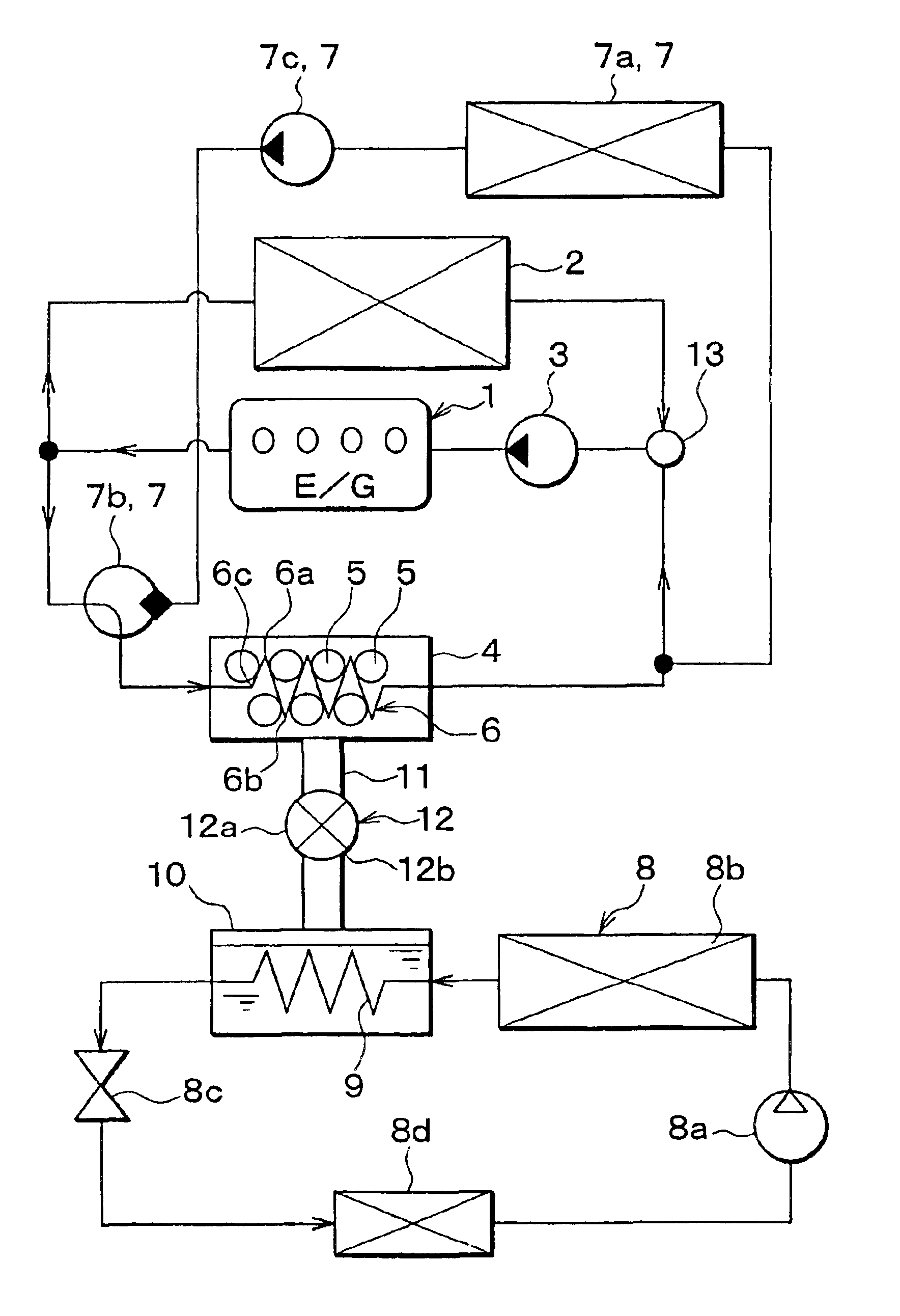
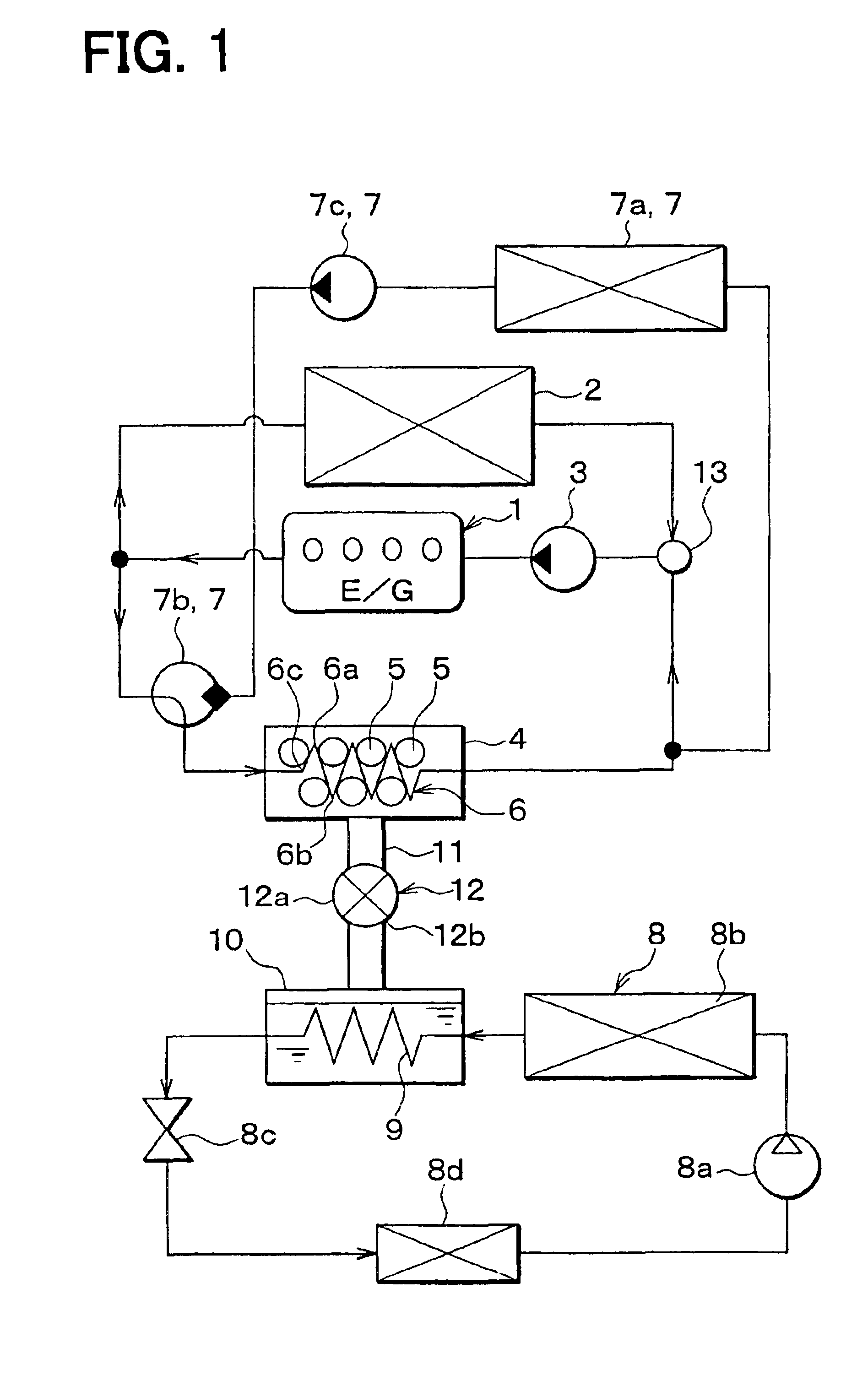
In the first embodiment, the present invention is typically applied to a vehicle including an internal combustion engine, and a heat storage system for a vehicle according to the first embodiment is schematically shown in FIG. 1. An engine 1 is an internal combustion engine that is used as a drive source for driving the vehicle, and a radiator 2 cools cooling water having circulated in the engine 1 by performing heat-exchange between outside air and the cooling water from the engine 1. A pump 3 circulates the cooling water by using motive power obtained from the engine 1.

An adsorption core 6, including adsorbents 5 adhered to a surface thereof, is disposed in an adsorption chamber 4. As a temperature of the adsorbent 5 increases, an amount of medium capable of being adsorbed on the adsorbent 5 (medium-adsorbing capacity of the adsorbent 5) is reduced. Further, when vaporized medium (gas medium) is adsorbed on the adsorbent 5, the adsorbent 5 generates heat. In the ...

second embodiment

(Second Embodiment)

In the second embodiment, as shown in FIG. 6, the radiator 2 and the heat storage radiator 7a are integrated with each other. Specifically, as shown in FIG. 7, the integrated radiator includes plural tubes 2a in which cooling water flows, header tanks 2b, 2c, and a separator 2d for partitioning a space in the header tank 2c at a water outlet side. The header tanks 2b, 2c communicate with tubes 2a at both ends of the tubes 2a in its longitudinal direction, respectively. As shown in FIG. 6, a three-way switching valve 14 switches any one of a cooling water stream from the radiator 2 and a cooling water stream from the heat storage radiator 7a.

In the second embodiment, the other parts are similar to those of the above-described first embodiment. Therefore, in the second embodiment, one of the heat storage mode, the warm-up / auxiliary-cooling mode and the auxiliary-cooling priority mode can be selected similar to the above-described first embodiment.

third embodiment

(Third Embodiment)

In the third embodiment shown in FIG. 8, the apparatuses constructing the adsorbent cooling unit 7 such as the heat storage radiator 7a described in the first embodiment, are eliminated, thereby simplifying the construction of the heat storage system.

Even in the third embodiment, the other parts are similar to those of the above-described first embodiment. Therefore, in the third embodiment, one of the heat storage mode, the warm-up / auxiliary-cooling mode and the auxiliary-cooling priority mode can be selected similar to the above-described first embodiment.


PUM

PropertyMeasurementUnit
temperatureaaaaaaaaaa

Abstract

In a heat storage system for a vehicle, when a temperature of cooling water from a vehicle engine is high, adsorbents are heated by the cooling water, so that moisture is desorbed from the adsorbents in order to store heat. When the temperature of cooling water is low, the moisture is adsorbed in the adsorbents to heat the cooling water, while refrigerant in a vapor compression refrigerator is cooled by evaporating water. Thus, adsorption heat is generated from the adsorbents, and the cooling water is heated by using the adsorption heat. Accordingly, warm-up operation of the vehicle engine is facilitated, while motive power consumed by the vapor compression refrigerator can be reduced.

Description

This application is related to and claims priority from Japanese Patent Applications No. 2002-60734 filed on Mar. 6, 2002 and No. 2002-182869 filed on Jun. 24, 2002, the contents of which are hereby incorporated by reference.1. Field of the InventionThe present invention relates to a heat storage system for a vehicle, which stores heat by using waste heat from the vehicle. The heat storage system includes an adsorbent for adsorbing and desorbing a medium. The heat storage system is suitably used for a heating system of a vehicle engine, and is also suitably used for a vehicle air conditioner.2. Description of Related ArtIn a system disclosed in JP-A-1-267346, waste heat, generated in traveling of a vehicle, is chemically absorbed while reaction gas is emitted, so that the waste heat is chemically stored. When operation of a vehicle engine is started, the reaction gas is adsorbed, so that the chemically stored heat is emitted to enhance warm-up operation of the vehicle engine. Howeve...

Claims


Application Information

Patent Timeline
Patent Type & Authority Patents(United States)
IPC IPC(8): B60H1/32B60H1/00F01P11/14F01P11/20
CPCB60H1/00492B60H1/00878B60H1/3201F01P2011/205B60H2001/00928B60H2001/00949B60H1/32014
Inventor AIKAWA, YASUKAZUSUZUKI, TAKAHISAINOUE, SATOSHISATO, HIDEAKIMIEDA, HIROSHI
Owner DENSO CORP
Why Eureka
Try Eureka