
Apparatus for fabricating powdery thermoelectric material and method of fabricating powdery thermoelectric material using the same

a technology of thermoelectric material and apparatus, which is applied in the manufacture/treatment of thermoelectric devices, manufacturing tools, thermoelectric devices, etc., can solve the problems of difficult high speed rotation, increased weight of disks, and easy to get off the rotational balance of disks, so as to reduce weight and high yield , the effect of high strength

Inactive Publication Date: 2004-10-26
KOMATSU LTD
View PDF5 Cites 5 Cited by
  • Summary
  • Abstract
  • Description
  • Claims
  • Application Information

AI Technical Summary

Benefits of technology

The present invention provides a method and apparatus for fabricating a powdery thermoelectric material using a rotating disk method. The invention aims to prevent solidification of molten metal and fabricate a fine powder with a high yield. The apparatus includes a container for mixing raw material, a funnel or pouring port for pouring the molten metal, and a rotating disk made of silicon nitride or a material containing silicon nitride for scattering the poured molten metal. The rotating disk has reduced weight, high mechanical strength, lower thermal expansion coefficient, and less reactivity with the materials. The method involves heating and melting the raw material, pouring it onto the rotating disk, and scattering it with the rotating disk to form fine globular forms, which are then cooled to prepare a powdery thermoelectric material. The resulting material has improved properties and can be used in thermoelectric modules.

Problems solved by technology

However, since conventional disks have large disk diameter and mass, it is difficult to rotate them at high speed.
As a result, the disk is further increased in the weight and difficult to be rotated at high speed, and it is easy to get off the rotational balance of the disk.
Further, this lowers the yield of the powdery thermoelectric material.
In order to improve these points (subjects), for example, when the weight of the disk is decreased for enabling high speed rotation and reducing the heat capacity, mechanical strength is lost since the thickness of the disk is decreased.
Further, when a metal (material) is used as the material for the disk, since the coefficient of thermal expansion is large, the material is strained by thermal stress to possibly worsen the durability.
Further, there is still left a problem that the molten metal is deprived of its heat by the disk and is easy to solidify on the disk to lower the powder yield.

Method used


Image

  • Apparatus for fabricating powdery thermoelectric material and method of fabricating powdery thermoelectric material using the same
  • Apparatus for fabricating powdery thermoelectric material and method of fabricating powdery thermoelectric material using the same
  • Apparatus for fabricating powdery thermoelectric material and method of fabricating powdery thermoelectric material using the same

Examples


Embodiment Construction

(This invention is to be described by way of preferred embodiments with reference to the drawings. Throughout the drawings, identical constituent elements carry the same reference numerals for which duplicate explanations are to be omitted.) Now, embodiments of the present invention will be described with reference to the drawings. By the way, same reference numbers shall be assigned to the same constituents, which shall be omitted from description.

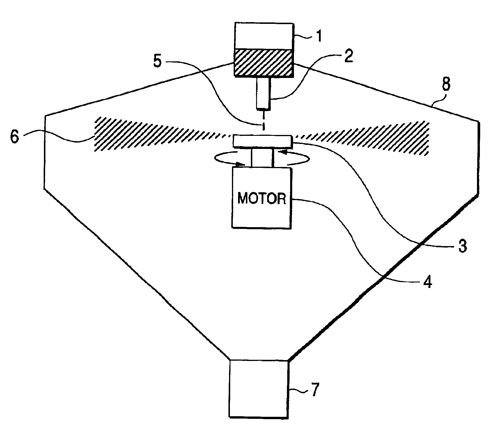
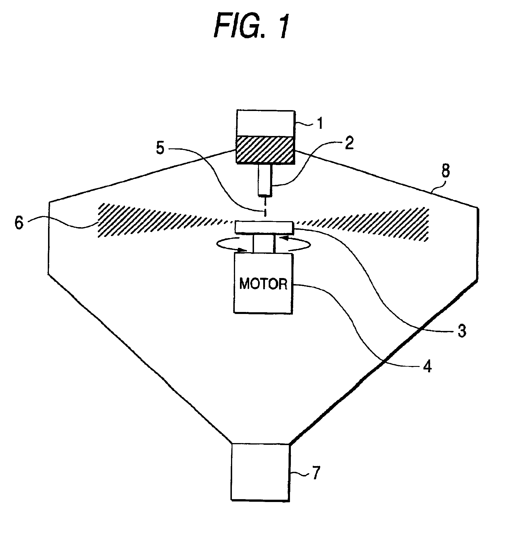
FIG. 1 is a schematic view showing an apparatus for fabricating a powdery thermoelectric material in one embodiment according to this invention.

The apparatus includes a vessel 1 disposed in a chamber 8, a funnel 2, a rotating disk 3, a motor 4 and a powder collecting portion (unit) 7.

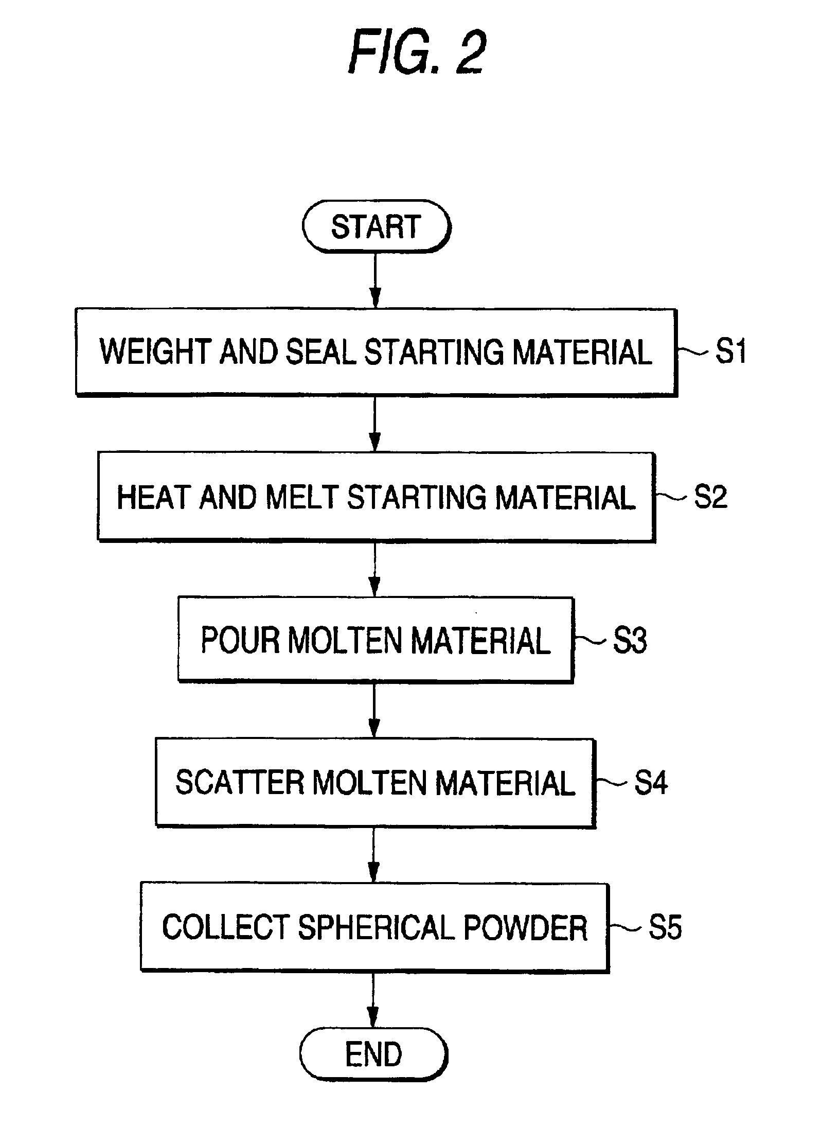
Further, FIG. 2 is a flow chart showing a method of fabricating a powdery thermoelectric material of one embodiment according to the present invention. The method of fabricating the powdery material in one embodiment according to this invention is to be expla...


PUM

PropertyMeasurementUnit
diameteraaaaaaaaaa
grain size particle diameteraaaaaaaaaa
temperatureaaaaaaaaaa

Abstract

An apparatus for fabricating a powdery thermoelectric material comprising a rotating disk having durability to thermal shock, having no reactivity with raw material and capable of high speed rotation, the apparatus comprising a container for mixing raw material of predetermined composition and heating and melting the same, a funnel or a pouring port for pouring the molten metal of the heat-melted raw material and a rotating disk made of silicon nitride or a material containing silicon nitride for scattering the poured molten metal.

Description

1. Field of the InventionThe present invention relates to an apparatus and method for fabricating a powdery thermoelectric material in order to fabricate a thermoelectric module that performs the conversion between thermal energy and electric energy.2. Description of the Related ArtA "thermoelectric phenomenon" is the general term of the Seebeck effect, the Peltier effect and the Thomson effect, and elements utilizing the phenomenon are called a "thermoelectric element", a "thermocouple", an "electronic cooling element", etc. The thermoelectric phenomenon was originally discovered between different kinds of metals, but in recent years, thermoelectric materials of semiconductors have come to be obtained, and conversion efficiencies not observed with metal materials have come to be attained. Elements employing the thermoelectric semiconductor materials are structurally simple and easy of handling, and can maintain stable characteristics, so that their uses in a wide range attract publ...

Claims


Application Information

Patent Timeline
Patent Type & Authority Patents(United States)
IPC IPC(8): H01L35/00H01L35/34B22F9/02B22F9/10H01L35/16H01L35/32
CPCH01L35/34Y10T29/41H10N10/01
Inventor KONISHI, AKIO
Owner KOMATSU LTD
Learn More