
Retardation plate and fabrication method thereof, and plate for circularly polarizing light, ½ wave plate and reflection-type liquid crystal display device utilizing the retardation plate

a technology of retardation plate and fabrication method, which is applied in the direction of polarizing elements, instruments, optics, etc., can solve the problems of reducing performance, increasing the cost of coating an adhesive material onto the chip, and reducing performan

Inactive Publication Date: 2004-11-02
FUJIFILM CORP +1
View PDF9 Cites 38 Cited by
  • Summary
  • Abstract
  • Description
  • Claims
  • Application Information

AI Technical Summary

Problems solved by technology

Further, adhering the two sheets of chips results not only in the increased costs of coating an adhesive material onto the chips, and chipping and adhering them, but also results in reduced performance due to angle shifts and the like when the chips are adhered.
Moreover, in a laminated type retardation plate formed by adhesion of the chips, there may be a problem of reduced performance due to increased thickness.

Method used


Image

  • Retardation plate and fabrication method thereof, and plate for circularly polarizing light, ½ wave plate and reflection-type liquid crystal display device utilizing the retardation plate
  • Retardation plate and fabrication method thereof, and plate for circularly polarizing light, ½ wave plate and reflection-type liquid crystal display device utilizing the retardation plate
  • Retardation plate and fabrication method thereof, and plate for circularly polarizing light, ½ wave plate and reflection-type liquid crystal display device utilizing the retardation plate

Examples


example 1

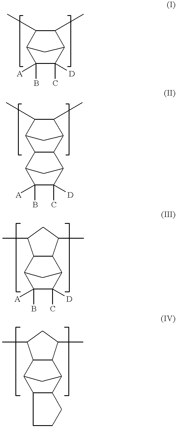
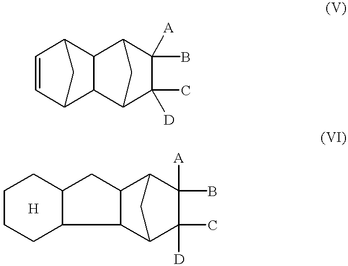
As a material including a negative intrinsic double refraction value, polystyrene (HRM2211L made by Shin Nippon Steel Chemical, Co., Ltd.) was used, and as a material including a positive intrinsic double refraction value, a norbornene resin (Arton made by JSR, Co., Ltd.) was used. Both were blended at weight ratio of 23:77 (polystyrene: norbornene resin), and this was dissolved in a methylene chloride solution, thereby preparing a coating solution.

It should be noted that when the absolute value of retardation (Re) for the wavelengths of 450 nm and 550 nm are defined as Re(450) and Re (550), respectively, the (Re(450) / Re(550)) value of norbornene resin is 1.01, and the (Re(450) / Re(550)) value of polystyrene is 1.05. Both values are not the same, and the difference is 0.04.

The viscosity of the coating solution is 9.8 Pa.multidot.s (98 poise), and this coating solution is flowed onto a glass plate using a doctor blade, dried, and a transparent film having a thickness of 107 .mu.m was ...

example 2

The retardation plate obtained in Example 1 and the polarizing plate were adhered so that a lag axis of the relevant retardation plate and a transmission axis of the relevant polarizing plate were crossed at the crossing angle of 45.degree.. The chromatic dispersion of the Re value for this adhered body was measured using the retardation measurement device (KOBRA21DH made by Ohji Measurement, Co., Ltd.). The results are shown in FIG. 3.

As shown in FIG. 3, the (Re / wavelength) value of the relevant adhered body was approximately 0.25 for the entire visible region and the adhered body was a plate for circularly polarizing light showing a 1 / 4 wavelength property in a broad band. Moreover, the adhered body showed approximately uniform Re value in the center portion and the edge portion, and in the edge portion, whitening and the like were not generated.

example 3

"Game boy color" made by Nintendo, Co., Ltd. was taken to pieces, the polarizing plate and retardation plate for an player were removed, and instead of these, a plate for circularly polarizing light of Example 2 was mounted to thereby prepare a reflection-type liquid crystal display device. As a result, in this reflection-type liquid crystal display device, a clear white display was obtained. Moreover, white display was uniform and clear display in the whole region from the edge portion to the center portion was obtained.


PUM

PropertyMeasurementUnit
wavelengthsaaaaaaaaaa

Abstract

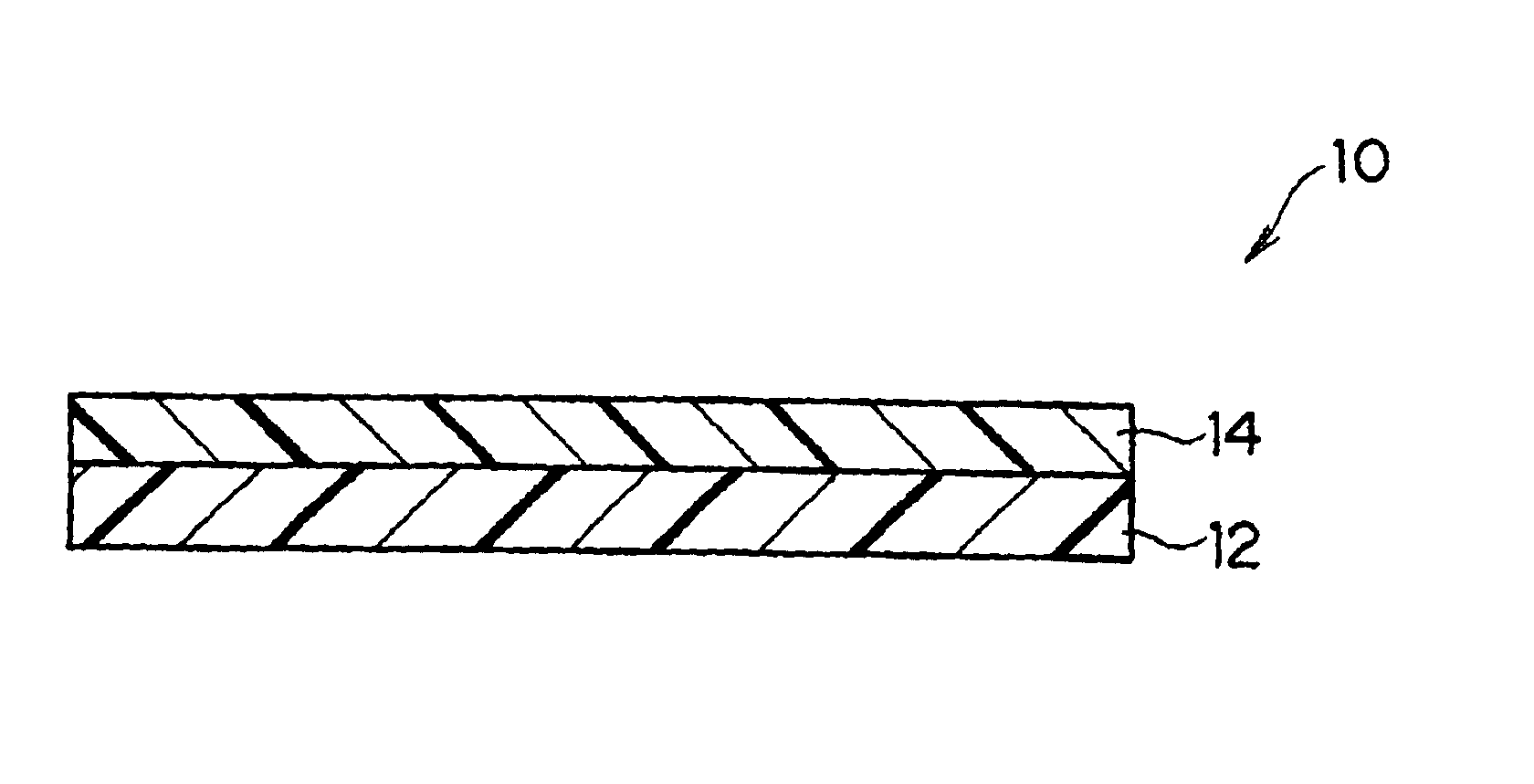
The present invention provides a broad band retardation plate that can be fabricated by a simple process and uniformly retards light incident of the entire visible light region. The retardation plate contains materials including positive or negative intrinsic double refraction values. When retardation values in wavelengths of 450 nm, 550 nm, and 650 nm are defined as Re(450), Re(550) and Re(650), respectively, the retardation plate satisfies the relational expression of Re(450)<Re(550)<Re(650). The retardation plate has a first layer comprising a positive material and a second layer comprising a negative material. The first layer and second layers have double refraction, and are laminated such that lag axes of the both layers are orthogonally crossed. It is preferable that the positive material is a norbornene based polymer and the like.

Description

1. Field of the InventionThe present invention relates to a retardation plate and a fabrication method thereof, and also relates to a plate for circularly polarizing light, a 1 / 2 wave plate and a reflection-type liquid crystal display device utilizing said retardation plate. More specifically, the invention relates to a retardation plate and a fabrication method thereof, and a plate for circularly polarizing light, a 1 / 2 wave plate and a reflection-type liquid crystal display device utilizing said retardation plate which can be used in display devices of personal computers, AV devices, portable information communication devices, game and simulation devices, and a navigation system for cars and the like.2. Description of the Related ArtA 1 / 4 wave plate whose retardation (Re) is 1 / 4 of a wavelength has a variety of uses. For example, it may be used in a reflection-type liquid crystal display device, in a pickup for an optical disk, in a glare proof film and the like. A 1 / 2 wave plate ...

Claims


Application Information

Patent Timeline
Patent Type & Authority Patents(United States)
IPC IPC(8): G02F1/13G02B5/30G02F1/13363
CPCG02B5/3083G02F1/13363G02F2001/133638G02F2001/133637G02F1/133637G02F1/133638G02F1/133528G02F1/133553
Inventor ARAKAWA, KOHEI
Owner FUJIFILM CORP
Learn More