Exposure method and apparatus

a technology of exposure method and apparatus, applied in the direction of photomechanical apparatus, instruments, printing, etc., can solve the problems of a stage apparatus based on a non-contact guide system that suffers from a relatively large pitch and amplitude along the guide surface, and achieves the effect of reducing the number of steps

Inactive Publication Date: 2004-11-02
NIKON CORP
View PDF19 Cites 60 Cited by
  • Summary
  • Abstract
  • Description
  • Claims
  • Application Information

AI Technical Summary

Problems solved by technology

However, the stage apparatus based on the non-contact guide system tends to suffer from the existence of waviness having a relatively large pitch and a relatively large amplitude along the guide surface, as compared with the contact type guide system.
Therefore, it has been feared that if the flatness of the running surface is unsatisfactory, the defocus amount remains corresponding to the product of the angle of inclination of the running surface and the distance from the pre-reading position to the exposure position.

Method used


Image

  • Exposure method and apparatus
  • Exposure method and apparatus
  • Exposure method and apparatus

Examples


Embodiment Construction

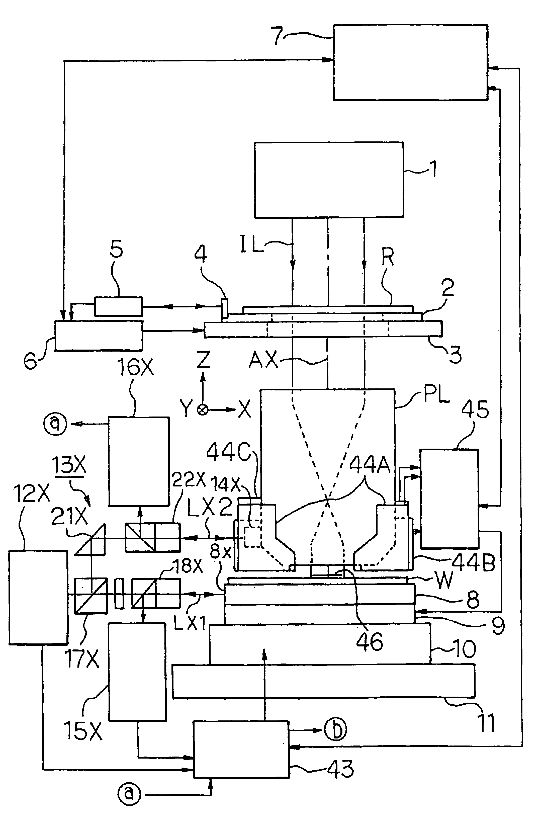
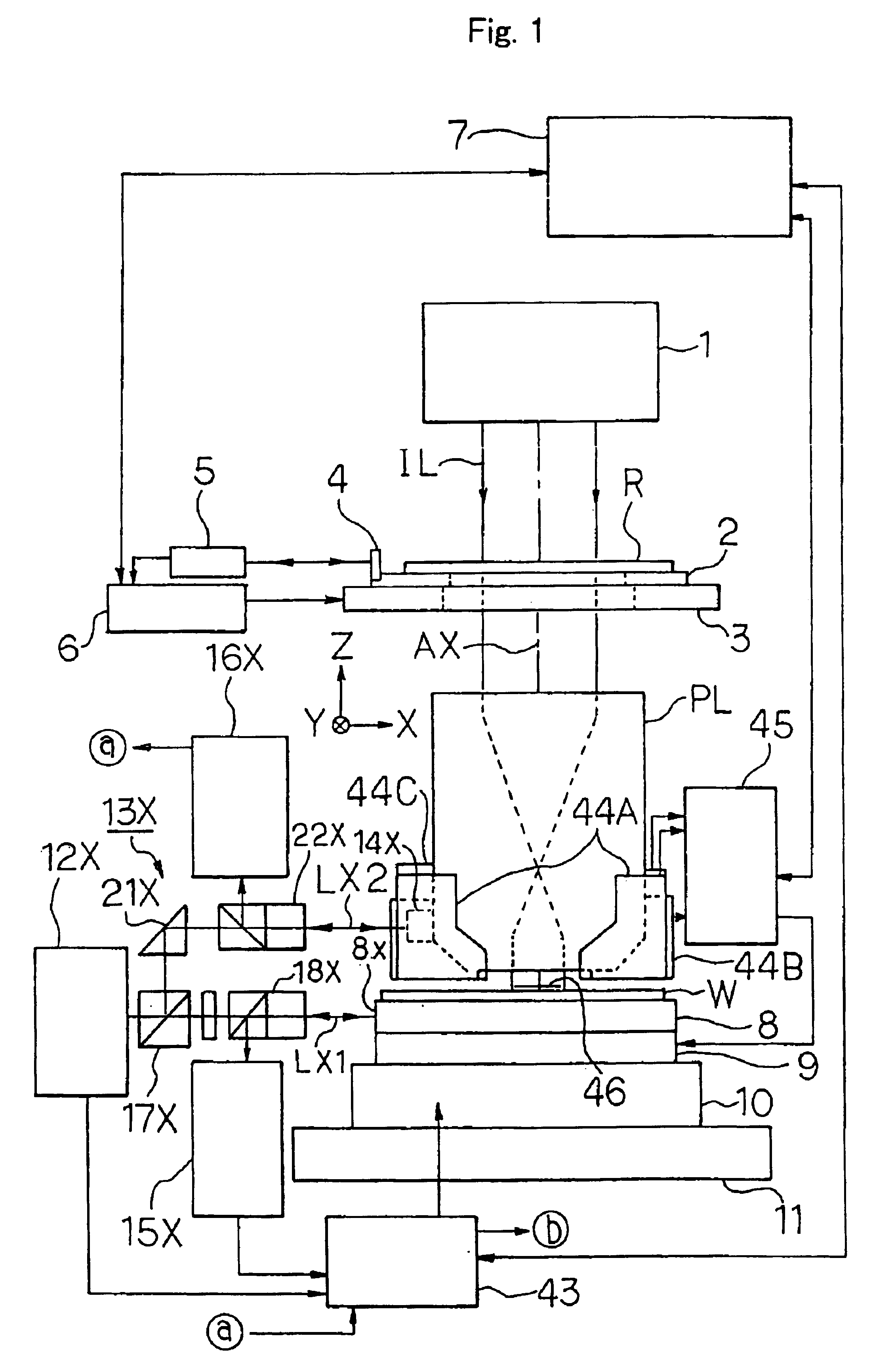
An exemplary preferred embodiment of the present invention will be explained below with reference to the drawings. In this embodiment, the present invention is applied to a projection exposure apparatus based on the step-and-scan system. FIG. 1 shows the projection exposure apparatus based on the step-and-scan system of this embodiment. In FIG. 1, when the exposure is performed, a slit-shaped illumination area on a pattern plane (lower surface) of a reticle R is illuminated with an exposure light beam IL such as an i-ray of a mercury lamp or an excimer laser beam radiated from an illumination optical system 1 including, for example, a light source, a fly's eye lens, a field diaphragm, and a condenser lens. A slit-shaped exposure area 46 on a wafer W applied with photoresist is exposed by projection with an image of the pattern in the illumination area on the reticle R under the exposure light beam IL at a predetermined projection magnification .beta. (for example, .beta. is 1 / 4 or 1...


PUM

PropertyMeasurementUnit
response frequencyaaaaaaaaaa
wavelengthaaaaaaaaaa
angleaaaaaaaaaa

Abstract

An exposure method is disclosed, in which a surface of a wafer can be conformed to an image plane highly accurately even when an angle of inclination of a running surface of a wafer stage is varied when a pattern for a semiconductor device or the like is transferred onto the wafer in accordance with the scanning exposure system. The focusing is performed in an exposure area on the basis of a focus position detected in a pre-reading area in which the focus position can be detected highly accurately although the detection range is narrow, disposed in front of the exposure area on the wafer in the scanning direction. In order to allow the surface of the wafer to be included in the detection range of the focus position in the pre-reading area, the focus position of the wafer is roughly conformed to the image plane on the basis of a result of detection at a rough detecting point for roughly detecting the focus position in front of the pre-reading area with a wide detection range.

Description

1. Field of the InventionThe present invention relates to an exposure method and an apparatus for being used to transfer a pattern such as a mask pattern to a photosensitive substrate in the photolithography step for producing, for example, semiconductor elements, image pickup elements (for example, CCD), liquid crystal display elements, or thin film magnetic heads. Especially, the present invention is preferably used for a projection exposure apparatus of the scanning exposure type such as the step-and-scan system.2. Description of the Related ArtFor example, when the semiconductor element is produced, the reduction projection type exposure apparatus (stepper) of the step-and-repeat system (full field exposure type) has been hitherto used in many cases as an exposure apparatus for transferring a pattern on a reticle as a mask to respective shot areas on a wafer applied with photoresist. Recently, on the other hand, in order to respond to such a request that a large area circuit pat...

Claims


Application Information

Patent Timeline
Patent Type & Authority Patents(United States)
IPC IPC(8): G03F7/20G03F9/00G03F7/207
CPCG03F7/70358G03F9/7034G03F9/70G03F7/70716
Inventor NISHI, KENJI
Owner NIKON CORP
Why Eureka
Try Eureka