Protection circuit for a battery cell

a protection circuit and battery cell technology, applied in the direction of safety/protection circuits, secondary cells servicing/maintenance, transportation and packaging, etc., can solve the problems of optimal li/socl.sub.2 cell performance, potential hazard for the tool and its battery, and increase the performance of the cell, so as to improve the protection

Inactive Publication Date: 2004-11-09
HALLIBURTON ENERGY SERVICES INC
View PDF27 Cites 28 Cited by
  • Summary
  • Abstract
  • Description
  • Claims
  • Application Information

AI Technical Summary

Benefits of technology

If desired, a delay element can be included in the protection circuit to slow the change in voltage across the transistor with short duration pulse loading. The delay element may comprise a resistor coupled to a capacitor to provide a desired R-C time constant. The delay element increases the performance of the cell by not activating the current limiting function of the transistor.
In a battery comprising a plurality of cells, each cell can have its own protection circuit, thereby providing improved protection in a multi-cell battery. The protection circuit, in fact, can be made in the form of a disk or wafer that physically is disposed between adjacent cells in a string of serially connected cells. It is also possible to include the protection circuit within each cell. In this way, the cell's voltage can be maintained at a safe level. These and other advantages will become apparent upon reviewing the following disclosure.

Problems solved by technology

Further, downhole tools usually experience relatively high temperatures presenting a potential hazard for the tool and its battery.
Two of the most prevalent conditions that interfere with optimal Li / SOCl.sub.2 cell performance are excessive anode "passivation" and cathode "freeze-over."
It is only when the cell is placed into service that passivation becomes a problem.
As current flows through the cell, the SEI layer begins to evaporate resulting in an associated increase in cell terminal voltage.
As noted above, the performance of Li / SOCl.sub.2 cells also can be detrimentally affected by cathode freeze-over which is the formation of LiCl discharge products in the outer portion of the cathode to the extent that it blocks the electrolyte's access to unused reaction sites.
Unlike passivated anodes, which can be recovered via a depassivation process, cathodes that have been frozen over are irreparably damaged and capacity loss will result.
Any load that results in a cell voltage below 3 V for a prolonged period of time may cause cathode damage and reduce cell capacity.
It is difficult to determine whether a few cells out of a hundred are passivated.
As explained below, this voltage drop can be harmful to the cell.
Also, cell voltage will generally decrease as a cell ages and nears the end of its useful life.
Forcing a cell below 2 V may cause bulging of the cell due to the build up of gaseous discharge products in the cell.
It is also widely known that lithium cells exhibit safety concerns when the cells are discharged into reversal (the cell voltage reverses polarity).
Manufacturers also warn that excessive loading of 3 or more cells in series has been known to result in venting caused by cell reversal.
This is particularly problematic for large strings of cells in a battery in which it is difficult to detect a few passivated cells out of numerous other depassivated cells in the battery.
Over driving a passivated cell in this manner may cause such problems as cell reversal and off gassing.
If one or more of the cells in the battery are passivated, the cell voltage for such cells may drop to a dangerous level.
Also, a cell that is not passivated, but is nearing the end of its useful life, may be unable to provide the necessary current at an acceptable voltage level.
As such, the voltage of such a nearly spent cell may be forced to a dangerously low level at the current level demanded by the load.

Method used


Image

  • Protection circuit for a battery cell
  • Protection circuit for a battery cell
  • Protection circuit for a battery cell

Examples


Embodiment Construction

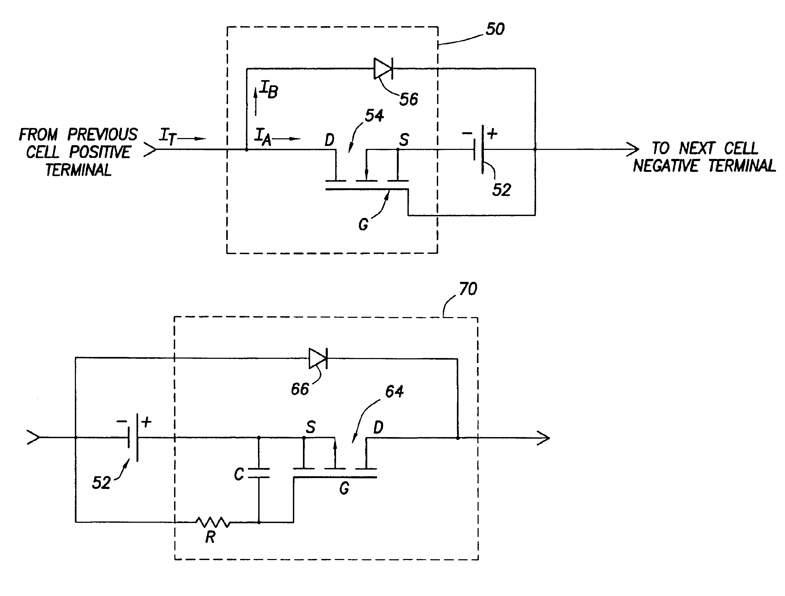
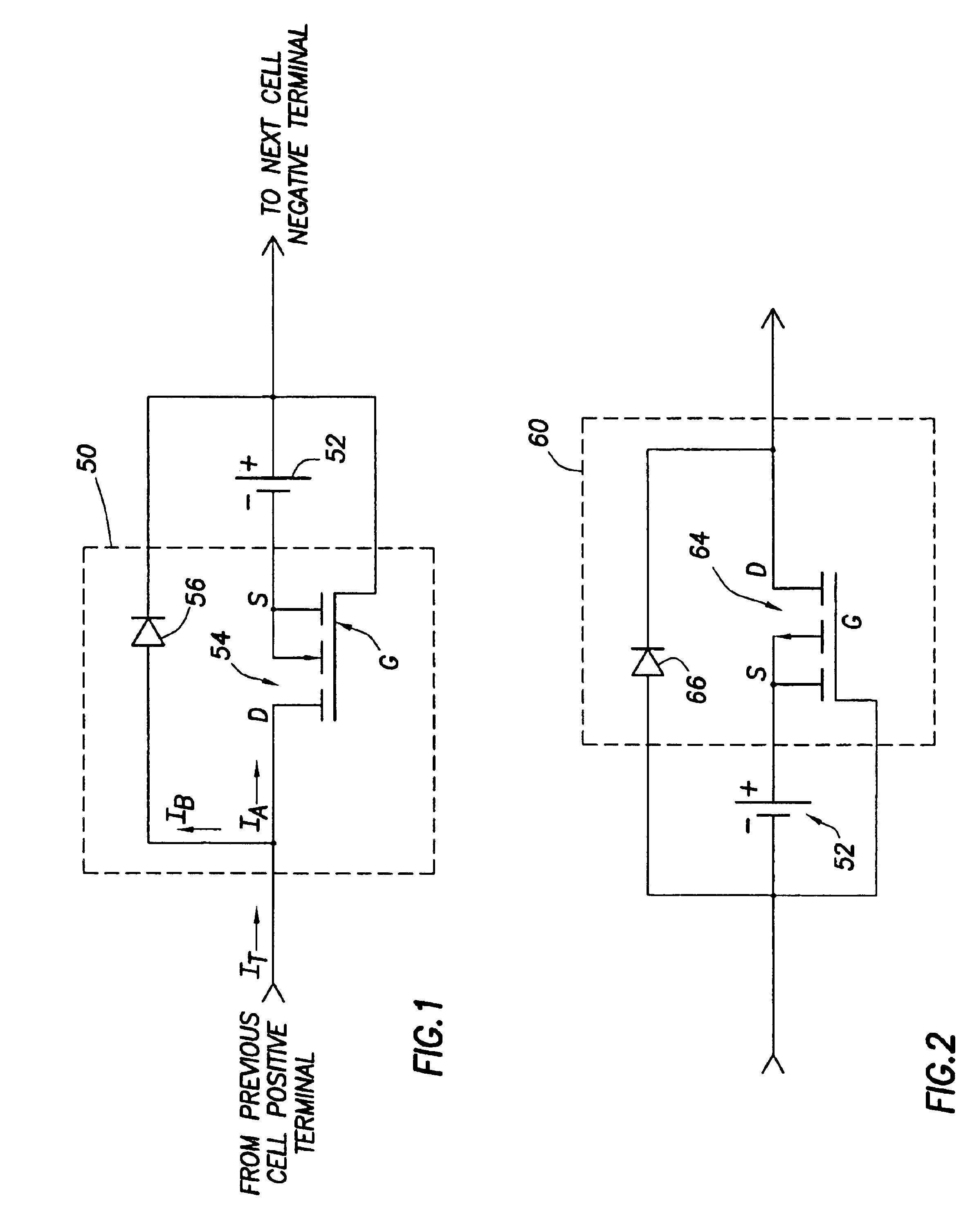
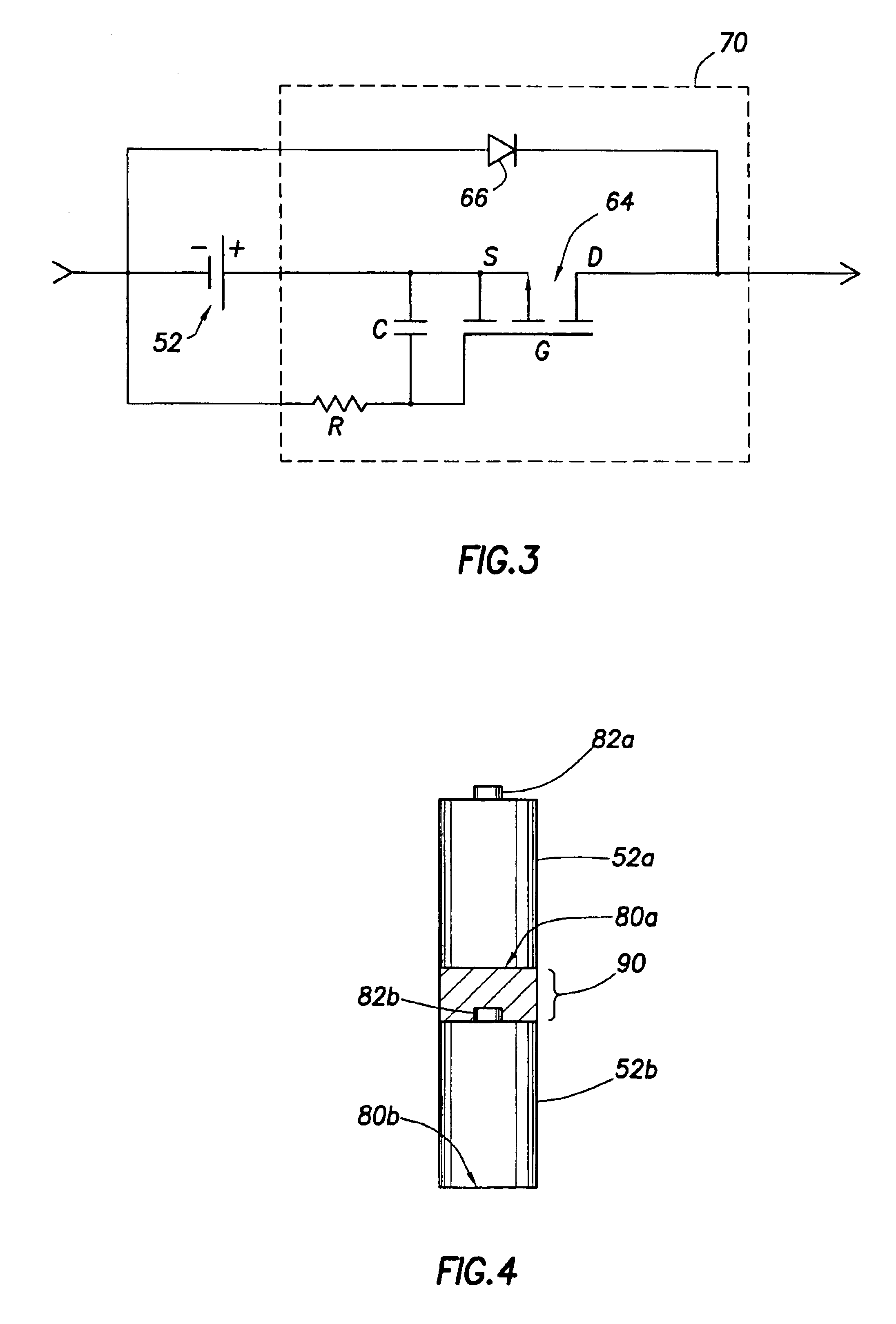
The problems noted above are solved in large part by a protection circuit which couples to and protects a cell. The protection circuit generally limits the current that can flow through the cell when the voltage across the cell falls to a predetermined minimum threshold. By limiting the current through the cell in this situation, the voltage on the cell will not fall below the minimum safe level.

In accordance with one embodiment of the invention, the protection circuit includes a transistor coupled in series with the cell and a bypass device coupled to both the transistor and the cell and in parallel with the transistor and cell. The transistor preferably comprises a metal oxide semiconductor field effect transistor ("MOSFET") and more preferably either an n-channel, enhancement mode MOSFET or a p-channel, enhancement mode MOSFET. The bypass device preferably comprises a diode that permits current to conduct around the cell being protected when the transistor limits the current thro...


PUM

PropertyMeasurementUnit
diameteraaaaaaaaaa
temperaturesaaaaaaaaaa

Abstract

A protection circuit couples to and protects a battery cell. The protection circuit generally limits the current that can flow through cell when the voltage across the cell falls to a predetermined minimum threshold, such as might occur if the cell is passivated, fails in service, or is reaching the end of its useful life. The protection circuit preferably includes a transistor, which couples in series with the cell and limits the current therethrough. By limiting the current through the cell when its voltage reaches a minimum threshold, the voltage on the cell will not fall below the minimum safe level. A bypass means (e.g., a diode) also is included to conduct current around the cell when its current has been limited by the transistor.

Description

Not applicable.Not applicable.1. Field of the InventionThe present invention generally relates to protecting battery cells from various fault conditions and unequal cell performance during normal operation. More particularly, the invention relates to a cell protection circuit that provides over-current protection to battery cells.2. Background InformationBatteries are useful for a variety of purposes, but generally must be operated in accordance with various criteria to ensure the safety and reliability of the battery and the device for which it provides power. The protection circuit described herein has been developed for use in connection with lithium batteries that are used in downhole tools. Such tools may be used for open hole logging and / or drilling purposes. Although the following background information and description of the protection circuit may be presented in the context of protecting high voltage, lithium battery packs, the protection circuit is useful for batteries use...

Claims


Application Information

Patent Timeline
Patent Type & Authority Patents(United States)
IPC IPC(8): H02J7/00
CPCH02J7/0031
Inventor GOODMAN, GEORGE D.
Owner HALLIBURTON ENERGY SERVICES INC
Why Eureka
Try Eureka