Mounting for a CMC combustion chamber of a turbomachine by means of flexible connecting sleeves

a technology of turbomachine and combustion chamber, which is applied in the direction of machines/engines, mechanical equipment, light and heating apparatus, etc., can solve the problems of inconvenient use, inconvenient manufacturing, and inability to meet the requirements of combustion chamber use, etc., and achieves the effect of reducing the drawbacks, simple in shape and easy manufacturing

Inactive Publication Date: 2004-11-30
SN DETUDE & DE CONSTR DE MOTEURS DAVIATION S N E C M A
View PDF14 Cites 39 Cited by
  • Summary
  • Abstract
  • Description
  • Claims
  • Application Information

AI Technical Summary

Benefits of technology

The present invention mitigates those drawbacks by proposing a casing-to-chamber connection having the ability to absorb the displacements induced by the differences between the expansion coefficients of those parts. Another object of the invention is to propose a structure that is simple in shape and that is particularly easy to manufacture.
By means of this direct attachment (integration) of the combustion chamber to the nozzle, any misalignment of the stream of gas in operation is avoided (thus guaranteeing better feed to the high pressure turbine), while also improving sealing between the combustion chamber and the nozzle. The connection to the shell via a system of sectorized flexible sleeves also provides an appreciable saving in weight for the combustion chamber compared with traditional connection devices having heavy rigid flanges.

Problems solved by technology

However, under certain particular conditions of use involving very high combustion temperatures, the use of a metal combustion chamber turns out to be completely unsuitable from a thermal point of view and it is necessary to make use of a combustion chamber based on high temperature composite materials of the CMC type.
However the difficulties involved in working such materials and their raw material costs mean that their use is usually restricted to the combustion chamber itself, with the high pressure turbine inlet nozzle and the casing continuing to be made more conventionally out of metal materials.
Unfortunately, metal materials and composite materials have coefficients of thermal expansion that are very different.
As a result, aerodynamic problems that are particularly severe arise at the interface with the nozzle at the inlet to the high temperature turbine, and in the connection between the casing and the chamber.

Method used


Image

  • Mounting for a CMC combustion chamber of a turbomachine by means of flexible connecting sleeves
  • Mounting for a CMC combustion chamber of a turbomachine by means of flexible connecting sleeves
  • Mounting for a CMC combustion chamber of a turbomachine by means of flexible connecting sleeves

Examples


Embodiment Construction

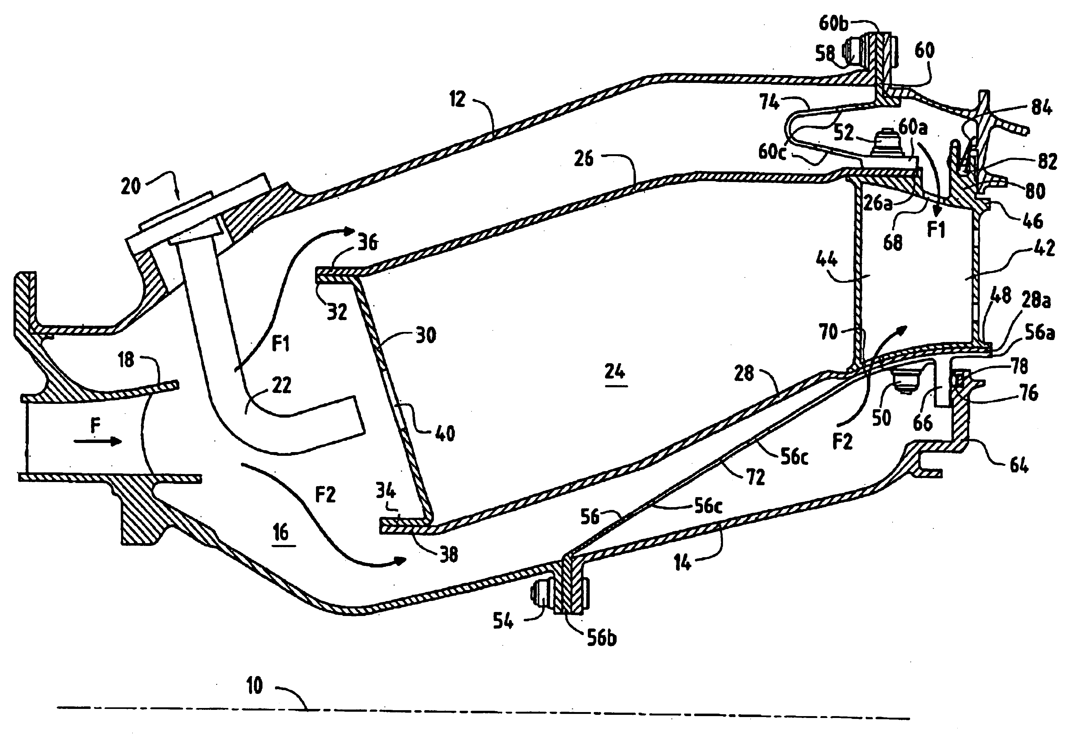
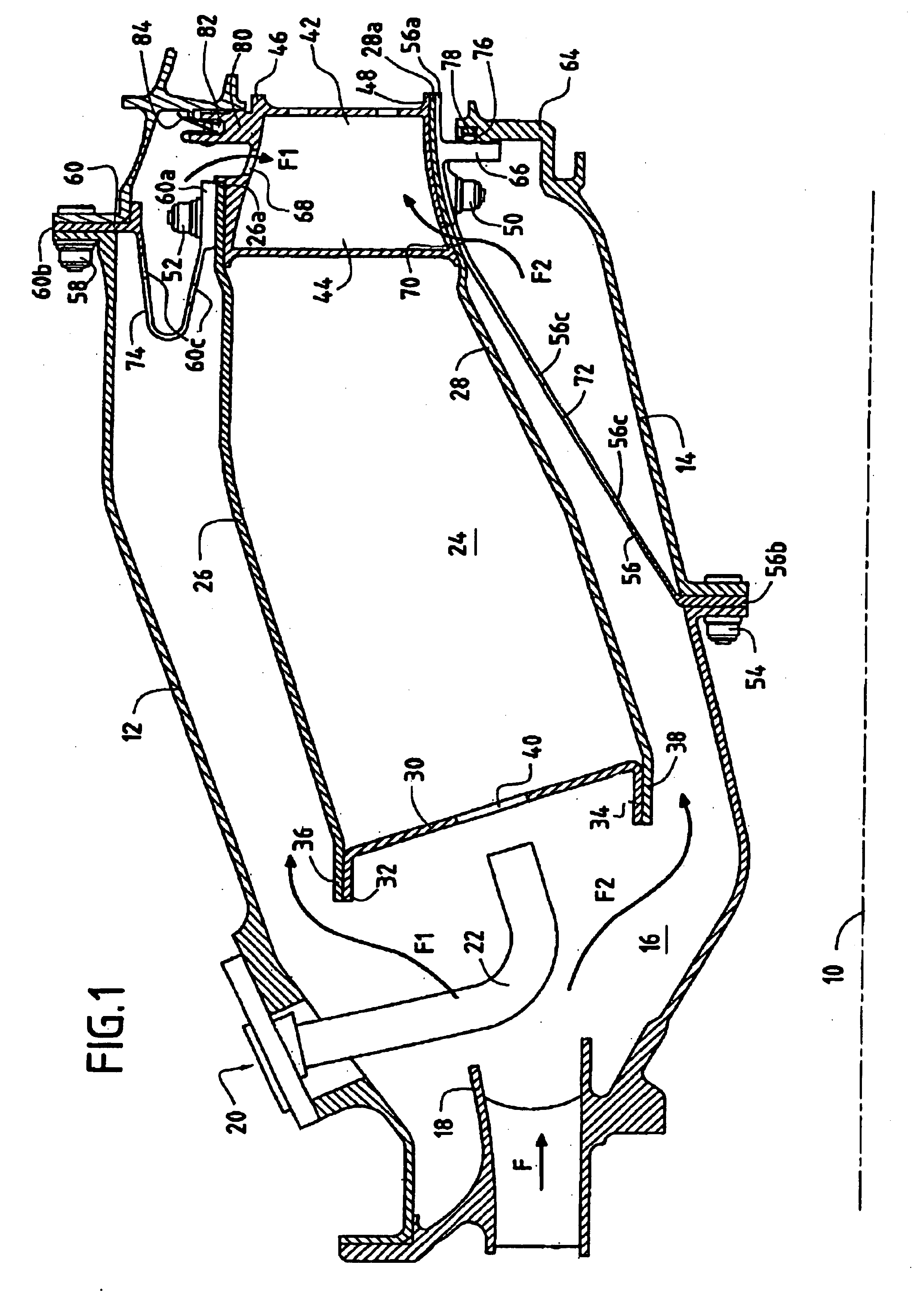
FIG. 1 is an axial half-section of the central portion of a turbojet or a turboprop (referred to generically as a "turbomachine" in the description below), comprising:

a shell having an outer annular wall (or case) 12 of metal material about a longitudinal axis 10 and an inner annular wall (or case) 14 that is coaxial therewith and likewise made of metal material; and

an annular space 16 extending between the two annular walls 12, 14 of said shell and receiving the compressed oxidizer, generally air, coming from an upstream compressor (not shown) of the turbomachine via an annular diffusion duct 18 defining a general gas flow direction F.

In the gas flow direction, this space 16 contains firstly an injection assembly made up of a plurality of injection systems 20 regularly distributed around the duct 18 and each comprising a fuel injection nozzle 22 fixed to the outer annular shell 12 (in order to simplify the drawings, the mixer and the deflector associated with each injection nozzle ...


PUM


Abstract

In a turbomachine comprising a metal material shell containing in a gas flow direction F: a fuel injection assembly; a composite material combustion chamber; and a metal material sectorized nozzle forming the inlet stage with fixed blades of a high pressure turbine, provision is made for the combustion chamber to be held by a sectorized flexible sleeve of metal material having one end fixed to the combustion chamber by first fixing means and a flange-forming opposite end fixed to the shell by second fixing means. The first fixing means also serve to connect the combustion chamber to the sectorized nozzle.

Description

The present invention relates to the field of turbomachines, and more particularly it relates to the interface between the high pressure turbine and the combustion chamber in turbojets having a combustion chamber that is made of ceramic matrix composite (CMC) material.PRIOR ARTConventionally, in a turbomachine, the high pressure turbine (HPT) and in particular its inlet nozzle, the combustion chamber, and also the casing (or "shell") for said chamber are all made of metal type materials. However, under certain particular conditions of use involving very high combustion temperatures, the use of a metal combustion chamber turns out to be completely unsuitable from a thermal point of view and it is necessary to make use of a combustion chamber based on high temperature composite materials of the CMC type. However the difficulties involved in working such materials and their raw material costs mean that their use is usually restricted to the combustion chamber itself, with the high pres...

Claims


Application Information

Patent Timeline
Patent Type & Authority Patents(United States)
IPC IPC(8): F23R3/60F23R3/00F23R3/50F23R3/42
CPCF23R3/60F05B2230/606
Inventor CONETE, ERICFORESTIER, ALEXANDREHERNANDEZ, DIDIER
Owner SN DETUDE & DE CONSTR DE MOTEURS DAVIATION S N E C M A
Why Eureka
Try Eureka