Touch panel switch

a technology of touch panel switch and switch body, which is applied in the direction of contacts, contact surface shape/structure, instruments, etc., can solve the problems of shrinkage in the effective usable area of input operation, and achieve the effect of preventing the deterioration of the first electrode, reducing the cost, and excellent convenien

Inactive Publication Date: 2004-12-14
PANASONIC CORP
View PDF10 Cites 20 Cited by
  • Summary
  • Abstract
  • Description
  • Claims
  • Application Information

AI Technical Summary

Benefits of technology

Since an insulating layer has an appropriate magnitude of elasticity, even when a pressing force is applied to the flexible insulating sheet in the vicinity of the area where the flexible insulating sheet and insulating substrate are fixed together, the insulating layer is deformed in the direction to reduce the thickness thereof in accordance with the bending of the flexible insulating sheet, thereby reducing a deforming stress imposed to the flexible insulating sheet and the first electrode disposed on the bottom surface thereof. As a result, the functional deterioration of the first electrode is suppressed and the area usable as a switch contact is expanded.
Furthermore, a thin film like second electrode is allowed to be formed on the flexible insulating sheet similarly as the first electrode is formed and, therefore, the flexible insulating sheet and bottom insulating sheet are prepared by the use of a common material, thereby a touch panel switch becomes available at a low cost.

Problems solved by technology

When the pushing action is repeated in the vicinity of the area of fixing together, the peripheral areas of a touch panel switch near the area of fixing together are not allowed to be used as input operation areas to act as switch contacts from the point of reliability due to the functional vulnerability of the plane electrodes.
As a result, a problem of shrinkage in the effectively usable area for an input operation is presented.

Method used


Image

  • Touch panel switch
  • Touch panel switch
  • Touch panel switch

Examples


exemplary embodiment 1

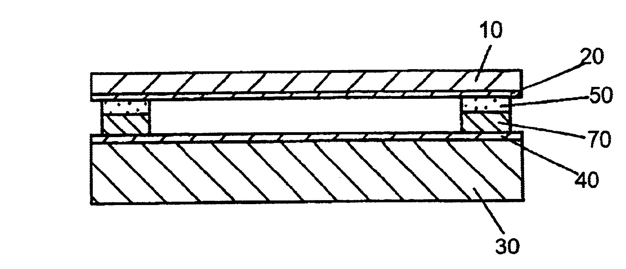
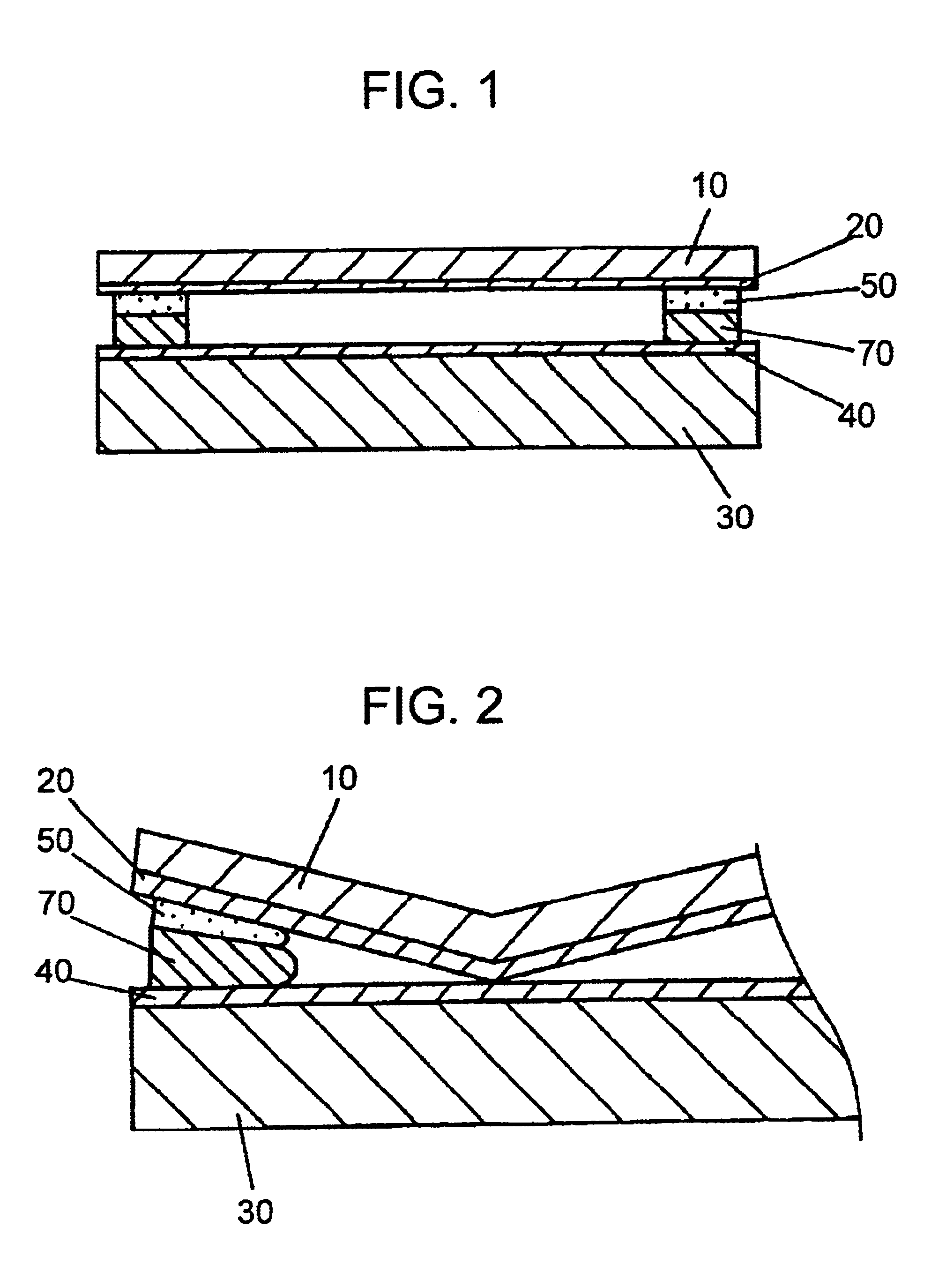
FIG. 1 is a cross-sectional view of a touch panel switch in exemplary embodiment 1 of the present invention. In FIG. 1, insulating sheet 10 is flexible, transparent, and is composed of such resins as polyethylene terephthalate, polyethersulfone, polyethylene naphthalate, polycarbonate, norbornene based resins and the like according to a drawing method or a casting method. Plane first electrode 20 composed of an optically transparent ITO thin film is deposited on the bottom surface of flexible insulating sheet 10 as mentioned above according to a sputtering method and the like.

On the other hand, insulating substrate 30 is a rigid substrate composed of such transparent materials as glass, polycarbonate, acrylic and the like and on the upper surface of insulating substrate 30 also is deposited plane second electrode 40 composed of an optically transparent ITO thin film according to a sputtering method and the like in the same way as in preparing first electrode 20.

Adhesive 50 with a pr...

exemplary embodiment 2

(Exemplary Embodiment 2)

A description is given to other touch panel switches in exemplary embodiment 2 of the present invention.

The same reference numeral as used in exemplary embodiment 1 is assigned to a part with the same structure as the one in exemplary embodiment 1.

FIG. 5 is a cross-sectional view of a touch panel switch in exemplary embodiment 2 of the present invention. In FIG. 5, different flexible sheet 12 is composed of such resins as polyethylene terephthalate, polyethersulfone, polyethylene naphthalate, polycarbonate, norbornene based resins and the like and formed to a transparent sheet-like configuration according to a drawing method or a casting method like insulating sheet 10 as described in exemplary embodiment 1.

Second electrode 40 composed of ITO is formed on aforementioned insulating sheet 12.

In addition, substrate 32 is a rigid body composed of such transparent materials as glass, polycarbonate, acrylic resin and the like and aforementioned insulating sheet 12 ...


PUM


Abstract

A touch panel switch having a wide usable operating range and thus a large effective use area and having electrodes disposed opposedly to each other through a spacer installed around the periphery thereof, the spacer formed in an elastic body of 1x10<5 >to 1x10<7 >dyne / cm<2 >in elastic modulus comprising an insulation layer and an adhesive layer, the insulation layer further comprising a clearance holding part with a uniform thickness and a gradient part with a thickness gradually decreasing from the clearance holding part into a substrate having the electrodes formed thereon.

Description

The present invention relates to a touch panel switch used as an input operation unit for electronic equipment to feed an input signal by pushing the touch panel switch with a finger, a pen and the like.In recent years, many flat touch panel switches have been used as an input operation unit for electronic equipment to perform an inputting operation by applying a small finger pressure, a pen and the like.Particularly, as portable small information equipment having a variety of functions is prevailing rapidly, the demand for transparent touch panel switches overlaid on a liquid crystal display (referred to as LCD, hereafter) to perform an input operation according to instructions displayed on the LCD, is growing.A description is given to a prior art touch panel switch as such with reference to the drawings.In order to facilitate the understanding of structural details of the touch panel switch, the drawings are prepared with the dimensions in thickness directions stretched.FIG. 6 is ...

Claims


Application Information

Patent Timeline
Patent Type & Authority Patents(United States)
IPC IPC(8): G06F3/033H01H13/712G06F3/041
CPCG06F3/041G06F3/0414H01H2227/006G06F3/045H01H13/70
Inventor FUKUI, TOSHIHARUOSAKI, TAKUOMOROI, HIROSHI
Owner PANASONIC CORP
Why Eureka
Try Eureka