Blade retention scheme using a retention tab

a technology of blade retention and tab, which is applied in the direction of propellers, propulsive elements, water-acting propulsive elements, etc., can solve the problems of requiring rework, unreliable riveting operation of bladed disk assemblies, and relatively expensive riveting machines

Inactive Publication Date: 2005-01-04
PRATT & WHITNEY CANADA CORP
View PDF21 Cites 51 Cited by
  • Summary
  • Abstract
  • Description
  • Claims
  • Application Information

AI Technical Summary

Benefits of technology

The invention provides a blade retention system, for use with a rotor hub disk with peripheral circumferential array of spaced apart blade retention slots extending between the forward and rearward hub faces, each slot having a radially inward floor and side walls adapted for sliding engagement with a blade root of a rotor blade. The blade root has a bottom surface which when engaged in the slot, is radially spaced from and adjacent the slot floor thus defining a gap extending between the forward and rearward hub faces at said selected broach angle. The blade root retention tab has an elongated web with a thickness less than said gap and including a preformed t

Problems solved by technology

The riveting operation on the bladed disk assembly is unreliable and frequently requires rework.
Riveting machines are relatively expensive and limit the location where the work can be performed.
Since blade tip clearance is of critical importance in maintaining the efficiency of the engine, variation in the outer rotor assembly diameter is undesirable.
As well, rivets have been known to develop insufficient axial resistance to the axial loads imparted on the blad

Method used


Image

  • Blade retention scheme using a retention tab
  • Blade retention scheme using a retention tab
  • Blade retention scheme using a retention tab

Examples


Embodiment Construction

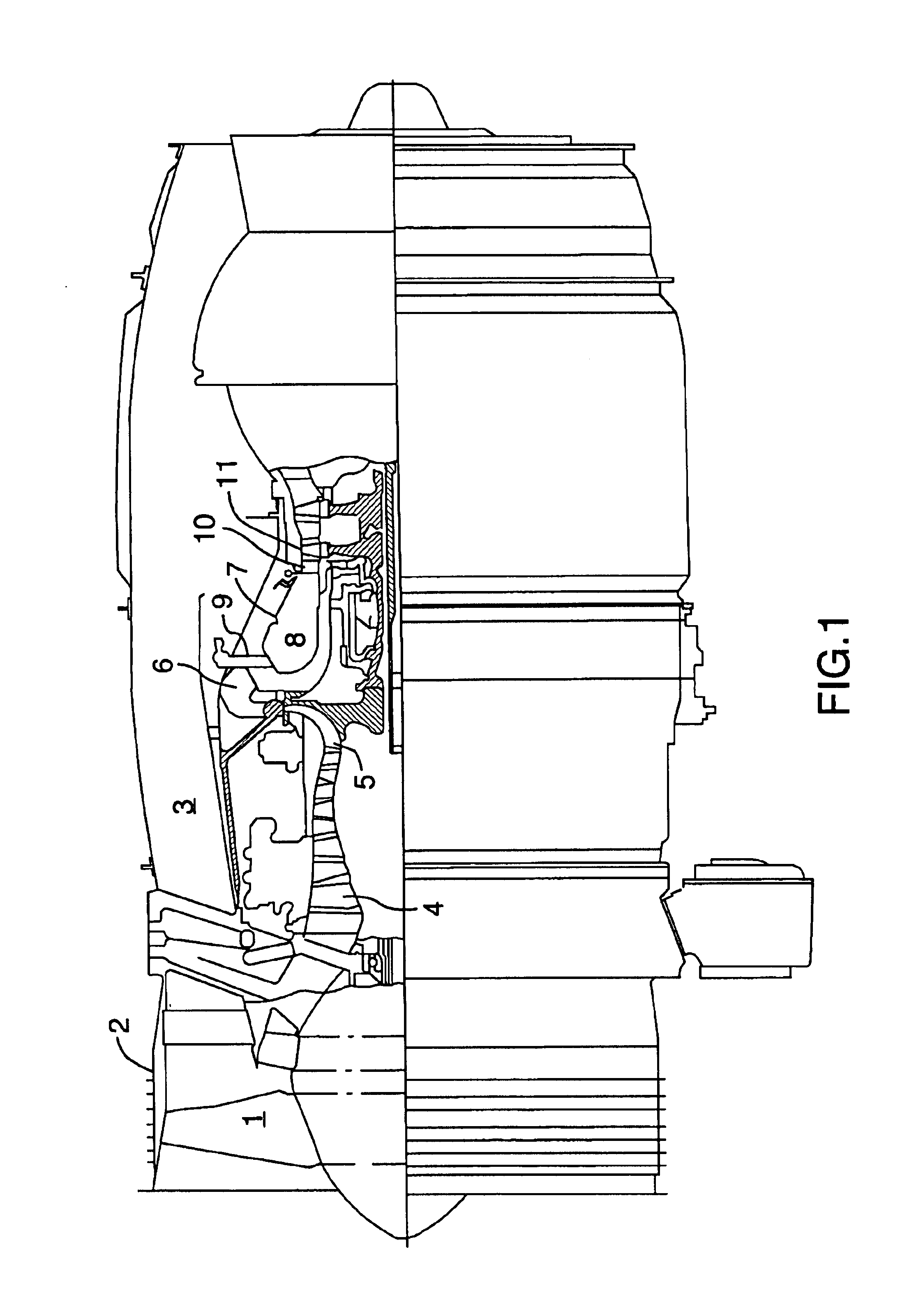
FIG. 1 shows an axial cross-section through a turbo-fan gas turbine engine. It will be understood however that the invention is equally applicable to any type of engine with a compressor and turbine section such as a turbo-shaft, a turbo-prop, or auxiliary power units. Air intake into the engine passes over fan blades 1 in a fan case 2 and is then split into an outer annular flow through the bypass duct 3 and an inner flow through the low-pressure axial compressor 4 and high-pressure centrifugal compressor 5. Compressed air exits the compressor 5 through a diffuser 6 and is contained within a plenum 7 that surrounds the combustor 8. Fuel is supplied to the combustor 8 through fuel tubes 9 which is mixed with air from the plenum 7 when sprayed through nozzles into the combustor 8 as a fuel air mixture that is ignited. A portion of the compressed air within the plenum 7 is admitted into the combustor 8 through orifices in the side walls to create a cooling air curtain along the combus...


PUM


Abstract

A blade retention system for retaining blade roots in slots of a rotor hub disk, the rotor blade having a radially outward blade tip requiring surface material removal by grinding to acquire a finished ground surface, having a blade root retention tab with an elongated web of thickness less than the gap between the slot and blade root and with at least two deformable protrusions extending radially to a height exceeding said gap, the protrusions adapted to deform under compression radially inwardly on sliding engagement with the blade root in the slot and to exert a reaction force radially outwardly on the blade root of a magnitude sufficient to secure the blade tip during surface removal grinding of the blade tip against radial displacement and against rotational displacement.

Description

TECHNICAL FIELDThe invention relates to a blade retention system with retention tab for securing blades to a rotor in a gas turbine engine.BACKGROUND OF THE ARTTurbine rotors and compressor rotors include individually removable blades that are conventionally mounted in a peripheral array of individually manufactured blades in interlocking slots in the rotor disc that match the blade roots. High rotational speeds require that the blades be securely mounted and blades are exposed to high temperature variations during operations as well as axial loading from flow of gas over the air foiled and platform surfaces. Individual blades are periodically removed during repairs and inspection. Preferably any blade locking mechanism is installed and rapidly removed with no damage to the rotor hub and blade root.Many different types of locking devices are provided in the prior art. One low cost method of retaining small blades is with counter sunken rivets, which extend through the slot. The rive...

Claims


Application Information

Patent Timeline
IPC IPC(8): F01D5/00F01D5/30
CPCF01D5/323
Inventor DI PAOLA, FRANCOGEKHT, EUGENE
Owner PRATT & WHITNEY CANADA CORP
Why Eureka
Try Eureka